
Pimoroni Pico Plus 2 W
Questi contenuti non sono ancora disponibili nella tua lingua.
The board as it appears on the Velxio canvas, with its full pin map
read live from the simulator (regenerated by scripts/gen-boards.mjs,
so it always matches what you can wire).
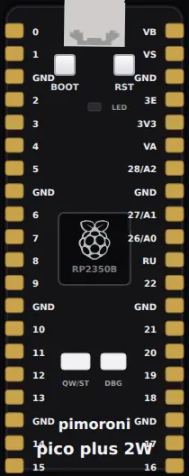
Family: Pro boards · Languages: Arduino C++
About this board
Section titled “About this board”Pimoroni’s RP2350B in the standard Pico footprint — GP0 through GP28 plus
the power rails — so any wiring you built for a
Pico drops straight onto it. What
the extra silicon adds: 16 MB of flash, 8 MB of PSRAM, a Raspberry Pi RM2
wireless module, a Qw/ST (Qwiic/STEMMA QT) connector on GP4/GP5, and a BOOT
button that doubles as a user switch on GP45.
Two board details that surprise people, on real hardware as much as here:
- The user LED is not a chip pin. It hangs off the RM2 module’s
WL_GPIO0—LED_BUILTINin Arduino,Pin('LEDW')in MicroPython — so it is driven by a command over the module’s SPI bus rather than a GPIO write. It lights here all the same. - The pads marked 26, 27 and 28 are two GPIOs each. The RP2350B’s ADC lives
on
GP40–GP47, nowhere near the Pico footprint, so Pimoroni tiedGP26+GP40,GP27+GP41andGP28+GP42together through a 1 kΩ resistor and silked each pad with both names —26 / A0and so on. That is whyanalogRead(A0)works andanalogRead(26)returns 0:A0isGP40. There is noA3pad;GP43is the on-board VSYS monitor.
What runs here: GPIO, UART, USB serial, I2C, SPI, ADC — including the on-die
temperature sensor, so analogReadTemp() returns a steady 27 °C — timers, the BOOT button,
the 8 MB PSRAM (pmalloc() returns real memory in the XIP window at
0x11000000) and WiFi — the CYW43439 inside the RM2 is emulated register by
register, so WiFi.begin() associates with Velxio’s virtual access point
(Velxio-GUEST, open), gets 10.13.37.42 and can make real HTTP requests through
Velxio’s network bridge. WiFi.scanNetworks() finds it too — one network,
Velxio-GUEST on channel 6, open, around -40 dBm, which is everything that is
on the air here. Not emulated: Bluetooth.
Start here
Section titled “Start here”- Onboard LED —
Pimoroni’s
onboard_led.py: blinks the user LED on the RM2. - Who is in space
— their
astronauts.py: joins WiFi and fetches a real HTTP response, live from open-notify.org. (Theircatfacts.pyis not shipped: catfact.ninja now redirects to HTTPS, and TLS is out of reach for the emulated chip.) - BOOT as user button
— their
button.py: hold BOOT (GP45) and the LED comes on. - The 8 MB PSRAM — allocates a megabyte outside the chip’s own 520 KB of SRAM and verifies it.
- Analog in on A0 —
a potentiometer on the pad silked
26 / A0, read asA0. - Qw/ST breakout bus
— scans the Qwiic connector on
GP4/GP5and reads the demo I2C devices, the pattern Pimoroni’s breakout examples use.
Pins (40)
Section titled “Pins (40)”- GP0
- GP1
- GND.1
- GP2
- GP3
- GP4
- GP5
- GND.2
- GP6
- GP7
- GP8
- GP9
- GND.3
- GP10
- GP11
- GP12
- GP13
- GND.4
- GP14
- GP15
- GP16
- GP17
- GND.5
- GP18
- GP19
- GP20
- GP21
- GND.6
- GP22
- RUN
- GP26
- GP27
- GND.7
- GP28
- ADC_VREF
- 3V3
- 3V3_EN
- GND.8
- VSYS
- VBUS
Every pin above is clickable on the canvas — click one to start a wire. Board-level behavior, quirks and example links live on the family page.