
示例:Romeo ESP32-S3 循迹机器人
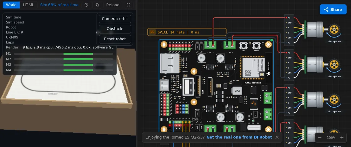
一台搭载 DFRobot Romeo ESP32-S3 的四轮机器人借助三个 Gravity 循迹传感器沿胶带环路行驶,并用 URM09 超声波传感器在障碍物前停车。固件是普通的 Arduino 代码;World 在其垫子上绘制机器人并为其提供四个传感器的数据。
打开它: velxio.dev/example/dfrobot-romeo-esp32s3-line-robot-3d 然后按 Run(运行)。
| 标识 | 元件 |
|---|---|
dfrobot-romeo-esp32s3 |
DFRobot Romeo ESP32-S3(板载四个 DRV8876 电机驱动) |
motorFL、motorFR、motorRL、motorRR |
带编码器的减速电机,50:1 |
lineL、lineC、lineR |
DFRobot Gravity 循迹传感器(SEN0017) |
urm09 |
DFRobot Gravity URM09 超声波,Trig 模式(SEN0388) |
| 从 | 到(Romeo ESP32-S3) |
|---|---|
motorFL M1 / M2 |
M1+ / M1- |
motorFR M1 / M2 |
M2+ / M2- |
motorRL M1 / M2 |
M3+ / M3- |
motorRR M1 / M2 |
M4+ / M4- |
lineL OUT |
GPIO 4 |
lineC OUT |
GPIO 5 |
lineR OUT |
GPIO 6 |
urm09 TRIG |
GPIO 16 |
| 每个传感器 VCC / GND | 3V3 / GND |
// DFRobot Romeo ESP32-S3 line-following robot (4WD) with a URM09 bumper.// Motors on the onboard DRV8876 drivers, PH/EN mode://   M1 front-left, M2 front-right, M3 rear-left, M4 rear-right.const int EN[4] = { 12, 14, 9, 47 };   // speed (PWM)const int PH[4] = { 13, 21, 10, 11 };  // direction (HIGH = forward)
// Gravity line trackers (SEN0017): LOW over the black tape, HIGH on white.const int LINE_L = 4, LINE_C = 5, LINE_R = 6;// Gravity URM09 Trig (SEN0388): one pin for trigger and echo.const int URM09 = 16;
const int CRUISE = 150;               // 0-255const int TURN_FAST = 170, TURN_SLOW = 40;const float STOP_CM = 15;
void side(bool left, int speed) {     // speed -255..255  int a = left ? 0 : 1, b = left ? 2 : 3;  bool fwd = speed >= 0;  int s = min(abs(speed), 255);  digitalWrite(PH[a], fwd ? HIGH : LOW); analogWrite(EN[a], s);  digitalWrite(PH[b], fwd ? HIGH : LOW); analogWrite(EN[b], s);}
void drive(int left, int right) { side(true, left); side(false, right); }
float readCm() {  pinMode(URM09, OUTPUT);  digitalWrite(URM09, LOW);  delayMicroseconds(2);  digitalWrite(URM09, HIGH); delayMicroseconds(10);  digitalWrite(URM09, LOW);  pinMode(URM09, INPUT);  unsigned long us = pulseIn(URM09, HIGH, 40000);  return us == 0 ? 500 : us / 58.0;}
int lastTurn = -1;                    // -1 left, +1 rightunsigned long lastPing = 0, lastPrint = 0;float cm = 500;
void setup() {  Serial.begin(115200);  for (int i = 0; i < 4; i++) pinMode(PH[i], OUTPUT);  pinMode(LINE_L, INPUT);  pinMode(LINE_C, INPUT);  pinMode(LINE_R, INPUT);  drive(0, 0);  Serial.println("Romeo line robot ready");}
void loop() {  if (millis() - lastPing >= 50) { lastPing = millis(); cm = readCm(); }
  bool L = digitalRead(LINE_L) == LOW;  bool C = digitalRead(LINE_C) == LOW;  bool R = digitalRead(LINE_R) == LOW;
  if (cm < STOP_CM) {    drive(0, 0);                                   // something ahead: wait  } else if (L && !R) {    drive(TURN_SLOW, TURN_FAST); lastTurn = -1;    // tape on the left  } else if (R && !L) {    drive(TURN_FAST, TURN_SLOW); lastTurn = +1;    // tape on the right  } else if (C) {    drive(CRUISE, CRUISE);                         // centred  } else if (lastTurn < 0) {    drive(-80, 150);                               // lost: search left  } else {    drive(150, -80);                               // lost: search right  }
if (millis() - lastPrint >= 500) { lastPrint = millis(); Serial.printf("line %d%d%d distance %.0f cm\n", L, C, R, cm); } delay(2);}本示例的 world.html 是为这台机器人编写的自由 World(参见
编写你自己的 World):一块 2.4 x 1.6 m 的垫子,
上面有一条 2.1 x 0.9 m、由 22 mm 黑色胶带构成的环路,以及一个机器人模型,
包含四个轮子、前方相距 18 mm 的三个循迹传感器,以及保险杠上的 URM09。
在 World 内部:
- Camera(相机)在环绕、跟随机器人和俯视之间循环切换。
- Obstacle(障碍物)在远处的直道上放下一个箱子。URM09 检测到它,固件会让机器人在它前面停下;再次按下即可移走箱子,机器人继续行驶。
- Reset robot(重置机器人)将其放回起点。
- 面板显示仿真时间、速度、三个循迹传感器、URM09 距离、圈数以及每个电机的驱动状态。
预期表现(基于 Velxio 对本示例自身的检查):绕环路一圈约需 16 秒仿真时间,偏离胶带从不超过 8 mm,并在箱子前 8 至 11 cm 处停下。固件在 15 cm 处做出判断;50 ms 的测距间隔和电机滑行解释了其余差距,与真实机器人上的情况一致。
- 修改
CRUISE和两个转向速度,观察机器人是切角还是冲出弯道。 - 修改
STOP_CM,按 Obstacle(障碍物),检查它停在哪里。 - 在串口监视器中把
millis()与循迹读数一起打印出来,并与 World 面板中的仿真时间对比:二者一致。