
例: Romeo ESP32-S3 ライントレーサー
DFRobot Romeo ESP32-S3 を搭載した4輪ロボットが、3つの Gravity ライントラッカーでテープのループをたどり、URM09 超音波センサーで障害物の手前で停止します。ファームウェアは通常の Arduino コードで、World がマット上にロボットを描画し、4つのセンサーに値を供給します。
開く: velxio.dev/example/dfrobot-romeo-esp32s3-line-robot-3d にアクセスし、Run を押します。
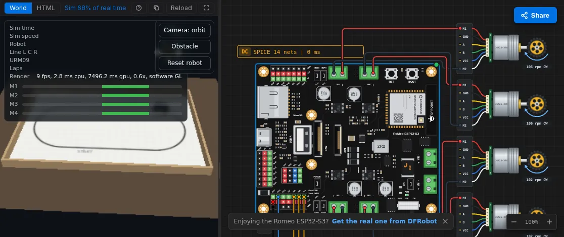
| Id | 部品 |
|---|---|
dfrobot-romeo-esp32s3 |
DFRobot Romeo ESP32-S3 (オンボードに DRV8876 モータードライバ4基) |
motorFL, motorFR, motorRL, motorRR |
エンコーダー付きギアモーター、50:1 |
lineL, lineC, lineR |
DFRobot Gravity ライントラッカー (SEN0017) |
urm09 |
DFRobot Gravity URM09 超音波、Trig モード (SEN0388) |
| 接続元 | 接続先 (Romeo ESP32-S3) |
|---|---|
motorFL M1 / M2 |
M1+ / M1- |
motorFR M1 / M2 |
M2+ / M2- |
motorRL M1 / M2 |
M3+ / M3- |
motorRR M1 / M2 |
M4+ / M4- |
lineL OUT |
GPIO 4 |
lineC OUT |
GPIO 5 |
lineR OUT |
GPIO 6 |
urm09 TRIG |
GPIO 16 |
| 各センサー VCC / GND | 3V3 / GND |
ファームウェア
Section titled “ファームウェア”// DFRobot Romeo ESP32-S3 line-following robot (4WD) with a URM09 bumper.// Motors on the onboard DRV8876 drivers, PH/EN mode:// M1 front-left, M2 front-right, M3 rear-left, M4 rear-right.const int EN[4] = { 12, 14, 9, 47 }; // speed (PWM)const int PH[4] = { 13, 21, 10, 11 }; // direction (HIGH = forward)
// Gravity line trackers (SEN0017): LOW over the black tape, HIGH on white.const int LINE_L = 4, LINE_C = 5, LINE_R = 6;// Gravity URM09 Trig (SEN0388): one pin for trigger and echo.const int URM09 = 16;
const int CRUISE = 150; // 0-255const int TURN_FAST = 170, TURN_SLOW = 40;const float STOP_CM = 15;
void side(bool left, int speed) { // speed -255..255 int a = left ? 0 : 1, b = left ? 2 : 3; bool fwd = speed >= 0; int s = min(abs(speed), 255); digitalWrite(PH[a], fwd ? HIGH : LOW); analogWrite(EN[a], s); digitalWrite(PH[b], fwd ? HIGH : LOW); analogWrite(EN[b], s);}
void drive(int left, int right) { side(true, left); side(false, right); }
float readCm() { pinMode(URM09, OUTPUT); digitalWrite(URM09, LOW); delayMicroseconds(2); digitalWrite(URM09, HIGH); delayMicroseconds(10); digitalWrite(URM09, LOW); pinMode(URM09, INPUT); unsigned long us = pulseIn(URM09, HIGH, 40000); return us == 0 ? 500 : us / 58.0;}
int lastTurn = -1; // -1 left, +1 rightunsigned long lastPing = 0, lastPrint = 0;float cm = 500;
void setup() { Serial.begin(115200); for (int i = 0; i < 4; i++) pinMode(PH[i], OUTPUT); pinMode(LINE_L, INPUT); pinMode(LINE_C, INPUT); pinMode(LINE_R, INPUT); drive(0, 0); Serial.println("Romeo line robot ready");}
void loop() { if (millis() - lastPing >= 50) { lastPing = millis(); cm = readCm(); }
bool L = digitalRead(LINE_L) == LOW; bool C = digitalRead(LINE_C) == LOW; bool R = digitalRead(LINE_R) == LOW;
if (cm < STOP_CM) { drive(0, 0); // something ahead: wait } else if (L && !R) { drive(TURN_SLOW, TURN_FAST); lastTurn = -1; // tape on the left } else if (R && !L) { drive(TURN_FAST, TURN_SLOW); lastTurn = +1; // tape on the right } else if (C) { drive(CRUISE, CRUISE); // centred } else if (lastTurn < 0) { drive(-80, 150); // lost: search left } else { drive(150, -80); // lost: search right }
if (millis() - lastPrint >= 500) { lastPrint = millis(); Serial.printf("line %d%d%d distance %.0f cm\n", L, C, R, cm); } delay(2);}この例の world.html は、このロボットのために書かれたフリーの World です (独自の World を作る を参照): 2.4 x 1.6 m のマットに 22 mm 幅の黒テープで 2.1 x 0.9 m のループが描かれ、ロボットのモデルには4つの車輪、前面に 18 mm 間隔で並ぶ3つのラインセンサー、そしてバンパー上の URM09 が備わっています。
World 内の操作:
- Camera は周回視点、ロボット追従、真上からの視点を切り替えます。
- Obstacle は遠い方の直線に箱を落とします。URM09 がそれを検知し、ファームウェアがロボットをその手前で停止させます。もう一度押すと箱が取り除かれ、ロボットは走行を再開します。
- Reset robot はロボットをスタート位置に戻します。
- パネルにはシミュレーション時間、速度、3つのラインセンサー、URM09 の距離、ラップ数、各モーターの駆動状態が表示されます。
期待される動作 (Velxio 自身によるこの例の検証で測定): ループ1周はシミュレーション時間で約16秒、テープから最大でも 8 mm しか外れず、箱の手前 8〜11 cm で停止します。ファームウェアは 15 cm で判断しますが、50 ms の ping 間隔とモーターの惰性が残りを説明します。これは実機のロボットでも同じです。
次に試すこと
Section titled “次に試すこと”CRUISEと2つの旋回速度を変更し、ロボットがコーナーをショートカットしたり行き過ぎたりする様子を観察します。STOP_CMを変更し、Obstacle を押して、どこで停止するか確認します。- シリアルモニターでラインの読み取り値の隣に
millis()を出力し、World のパネルのシミュレーション時間と比較します: 両者は一致します。