
Example: Romeo ESP32-S3 line follower
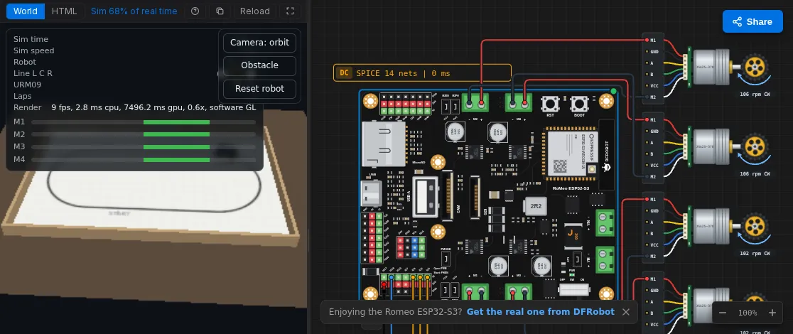
A four-wheel robot on the DFRobot Romeo ESP32-S3 follows a taped loop with three Gravity line trackers, and stops before an obstacle with a URM09 ultrasonic sensor. The firmware is plain Arduino code; the World draws the robot on its mat and feeds the four sensors.
Open it: velxio.dev/example/dfrobot-romeo-esp32s3-line-robot-3d and press Run.
| Id | Part |
|---|---|
dfrobot-romeo-esp32s3 |
DFRobot Romeo ESP32-S3 (four DRV8876 motor drivers on board) |
motorFL, motorFR, motorRL, motorRR |
Gear motor with encoder, 50:1 |
lineL, lineC, lineR |
DFRobot Gravity line tracker (SEN0017) |
urm09 |
DFRobot Gravity URM09 ultrasonic, Trig mode (SEN0388) |
Wiring
Section titled “Wiring”| From | To (Romeo ESP32-S3) |
|---|---|
motorFL M1 / M2 |
M1+ / M1- |
motorFR M1 / M2 |
M2+ / M2- |
motorRL M1 / M2 |
M3+ / M3- |
motorRR M1 / M2 |
M4+ / M4- |
lineL OUT |
GPIO 4 |
lineC OUT |
GPIO 5 |
lineR OUT |
GPIO 6 |
urm09 TRIG |
GPIO 16 |
| every sensor VCC / GND | 3V3 / GND |
Firmware
Section titled “Firmware”// DFRobot Romeo ESP32-S3 line-following robot (4WD) with a URM09 bumper.// Motors on the onboard DRV8876 drivers, PH/EN mode:// M1 front-left, M2 front-right, M3 rear-left, M4 rear-right.const int EN[4] = { 12, 14, 9, 47 }; // speed (PWM)const int PH[4] = { 13, 21, 10, 11 }; // direction (HIGH = forward)
// Gravity line trackers (SEN0017): LOW over the black tape, HIGH on white.const int LINE_L = 4, LINE_C = 5, LINE_R = 6;// Gravity URM09 Trig (SEN0388): one pin for trigger and echo.const int URM09 = 16;
const int CRUISE = 150; // 0-255const int TURN_FAST = 170, TURN_SLOW = 40;const float STOP_CM = 15;
void side(bool left, int speed) { // speed -255..255 int a = left ? 0 : 1, b = left ? 2 : 3; bool fwd = speed >= 0; int s = min(abs(speed), 255); digitalWrite(PH[a], fwd ? HIGH : LOW); analogWrite(EN[a], s); digitalWrite(PH[b], fwd ? HIGH : LOW); analogWrite(EN[b], s);}
void drive(int left, int right) { side(true, left); side(false, right); }
float readCm() { pinMode(URM09, OUTPUT); digitalWrite(URM09, LOW); delayMicroseconds(2); digitalWrite(URM09, HIGH); delayMicroseconds(10); digitalWrite(URM09, LOW); pinMode(URM09, INPUT); unsigned long us = pulseIn(URM09, HIGH, 40000); return us == 0 ? 500 : us / 58.0;}
int lastTurn = -1; // -1 left, +1 rightunsigned long lastPing = 0, lastPrint = 0;float cm = 500;
void setup() { Serial.begin(115200); for (int i = 0; i < 4; i++) pinMode(PH[i], OUTPUT); pinMode(LINE_L, INPUT); pinMode(LINE_C, INPUT); pinMode(LINE_R, INPUT); drive(0, 0); Serial.println("Romeo line robot ready");}
void loop() { if (millis() - lastPing >= 50) { lastPing = millis(); cm = readCm(); }
bool L = digitalRead(LINE_L) == LOW; bool C = digitalRead(LINE_C) == LOW; bool R = digitalRead(LINE_R) == LOW;
if (cm < STOP_CM) { drive(0, 0); // something ahead: wait } else if (L && !R) { drive(TURN_SLOW, TURN_FAST); lastTurn = -1; // tape on the left } else if (R && !L) { drive(TURN_FAST, TURN_SLOW); lastTurn = +1; // tape on the right } else if (C) { drive(CRUISE, CRUISE); // centred } else if (lastTurn < 0) { drive(-80, 150); // lost: search left } else { drive(150, -80); // lost: search right }
if (millis() - lastPrint >= 500) { lastPrint = millis(); Serial.printf("line %d%d%d distance %.0f cm\n", L, C, R, cm); } delay(2);}The World
Section titled “The World”This example’s world.html is a free World written for this robot (see
Write your own World): a 2.4 x 1.6 m mat with
a 2.1 x 0.9 m loop of 22 mm black tape, and a model of the robot with its
four wheels, three line sensors 18 mm apart across the front, and the URM09
on the bumper.
Inside the World:
- Camera cycles orbit, follow the robot, and from above.
- Obstacle drops a box on the far straight. The URM09 sees it and the firmware stops the robot short of it; press it again to take the box away and the robot drives on.
- Reset robot puts it back at the start.
- The panel shows simulated time, speed, the three line sensors, the URM09 distance, laps and each motor’s drive.
What to expect, measured on Velxio’s own check of this example: one lap of the loop in about 16 seconds of simulated time, never more than 8 mm off the tape, and a stop 8 to 11 cm before the box. The firmware decides at 15 cm; the 50 ms ping interval and the motors coasting account for the rest, as on a real robot.
Try next
Section titled “Try next”- Change
CRUISEand the two turn speeds and watch the robot cut or overshoot the corners. - Change
STOP_CM, press Obstacle, and check where it stops. - Print
millis()next to the line readings in the serial monitor and compare it with the simulated time in the World’s panel: they agree.