Most Arduino tutorials jump straight to code. But the parts around the microcontroller are analog: the resistor that keeps an LED alive, the divider that turns a sensor into a voltage, the transistor that switches a motor, the regulator that makes 5 V out of a wall adapter. When one of those is wrong, no amount of code fixes it.
Velxio simulates that half too. It runs ngspice, the open-source SPICE circuit simulator, compiled to WebAssembly, so resistors, capacitors, diodes, transistors, op-amps and regulators behave like their real counterparts in your browser. You can measure them with a voltmeter, an ammeter and an oscilloscope, and change any value while the circuit runs.
This article walks through seven projects. The first five have no microcontroller at all, just components. The last two mix analog circuits with an Arduino and an ESP32. Every project is in the example gallery, and every number below was read from the simulator and checked against the formula that explains it.
Before you start: the three instruments
- Circuits without a board run as soon as they open. Right-click any part to open its inspector and change its value there: a resistor’s resistance, a capacitor’s capacitance, a sensor’s light level or temperature. The circuit solves again with the new value.
- Voltmeter and ammeter are parts like any other: the voltmeter goes across what you want to measure, the ammeter in series. On a DC circuit they show one number. On an AC circuit they show the RMS value, the peak and the DC average, measured once the circuit has settled.
- The oscilloscope shows how a voltage changes over time. Right-click a wire and choose Add to scope; each channel scales itself to fit the signal. With a board on the canvas, stop the simulation first: while a sketch runs, the canvas keeps its clicks for the parts.
One thing to know: for circuits with AC sources, Velxio solves a short window of time from the moment the power comes on (a few cycles of the signal) and shows the scope trace of that window. It repeats the solve as you change things, so the picture stays current, but it is not a continuous recording.
1. An LED and a resistor: Ohm’s law
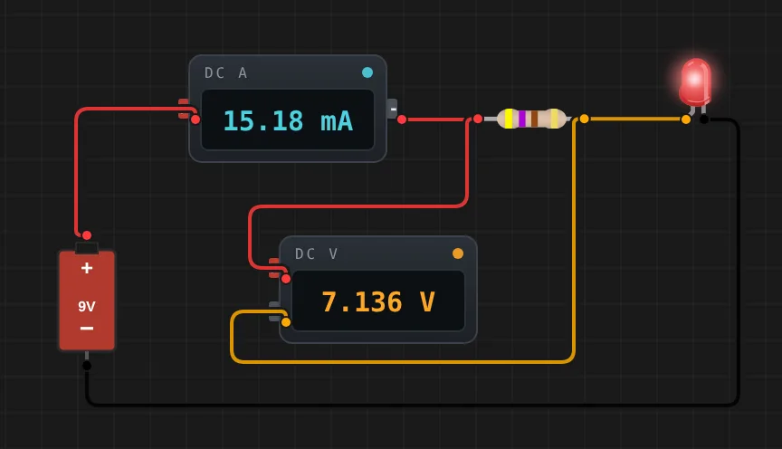
The first circuit every beginner builds, and the one most often built wrong: an LED connected straight to a battery burns out, because nothing limits its current. The resistor in series does that job.
The meters tell the whole story:
- The voltmeter across the 470 Ω resistor reads 7.136 V.
- The ammeter reads 15.18 mA. Ohm’s law says the same thing: 7.136 V / 470 Ω = 15.2 mA.
- The rest of the 9 V drops across the LED: about 1.84 V, the forward voltage of a red LED.
That is the formula for choosing the resistor: R = (Vsupply − VLED) / I. For 15 mA from a 9 V battery: (9 − 1.8) / 0.015 = 480 Ω, so 470 Ω is the nearest standard value.
Try it: right-click the resistor and change it to 1 kΩ. The current falls to 7.2 mA and the LED dims, while its own voltage barely moves (1.81 V). An LED holds its voltage nearly constant and lets the resistor set the current.
Open the LED and Ohm’s law circuit in Velxio
2. A 5 V power supply: rectifier, capacitor and regulator
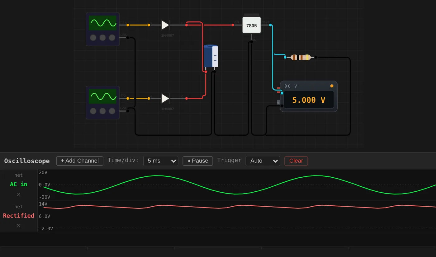
The classic linear power supply, the one inside every old wall adapter, in four stages:
- Transformer. It turns mains AC into a safer, lower AC voltage. Here it is a center-tapped 12-0-12 V secondary, drawn as two signal generators in antiphase (12 V peak each, 50 Hz).
- Rectifier. Two 1N4007 diodes, one per half of the secondary. Each conducts on its own half-cycle, so the output gets a positive pulse every 10 ms: full-wave rectification.
- Reservoir capacitor. The 220 µF capacitor charges at each peak and feeds the load in between. The voltage it holds is not flat: it sags between peaks. That sag is the ripple.
- Regulator. The 7805 takes that wobbly voltage and holds its output at exactly 5 V, as long as its input stays at least about 2 V above the output.
The scope picture at the top of this article shows the 12 V AC from the transformer and the rectified voltage across the capacitor. The capacitor swings between 10.1 V and 11.8 V, about 1.7 V of ripple with a 50 mA load, and the voltmeter on the output reads a steady 5.000 V.
The quick estimate for the ripple is ΔV ≈ I / (2·f·C): 0.05 A / (2 × 50 Hz × 220 µF) = 2.3 V. That formula assumes the capacitor feeds the load for the whole half-cycle; in reality the diodes recharge it a little before that, so the measured 1.7 V is lower.
Try it: right-click the capacitor and change it to 47 µF. The ripple grows to 6 V, the valleys fall to 5.9 V, below what the 7805 needs, and its output dips to 3.9 V on every cycle. That is why power supplies use big capacitors.
Open the 5 V power supply in Velxio
3. A night light with an LDR and two transistors
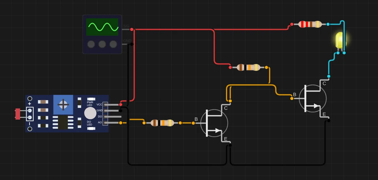
An automatic night light, with no microcontroller and no code. A light-dependent resistor (LDR) measures the light, and two transistors turn the LED on when it gets dark.
The light sensor module is a voltage divider: the LDR on top and a 10 kΩ resistor below. In daylight the LDR’s resistance is low and the module’s output (AO) is high; in the dark it climbs to hundreds of kΩ and AO falls toward 0 V.
- Q1 is the sensor’s switch. When AO is above about 0.6 V, Q1 conducts and pulls the base of Q2 down to almost 0 V.
- Q2 drives the LED. While Q1 is on, Q2 is off and the LED is dark. When the light falls, Q1 stops conducting, the 10 kΩ resistor pulls Q2’s base up, Q2 turns on and the LED lights.
Why two transistors? Because one alone would do the opposite: light the LED when it is bright. The first stage inverts the signal.
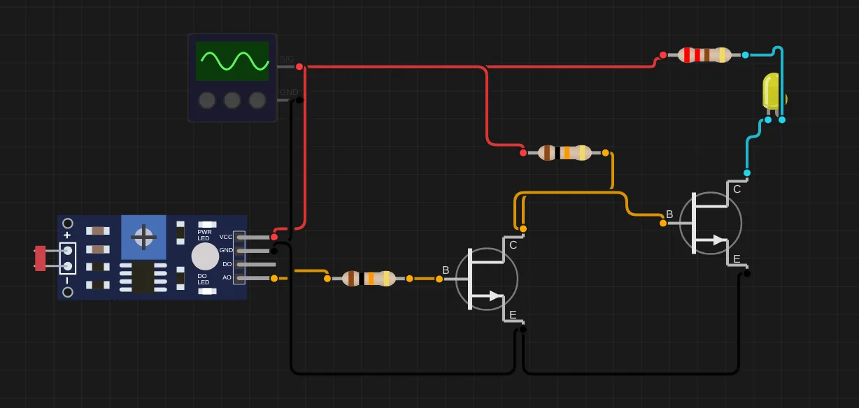
In the simulation, at 20 lux (a dim room) AO sits at 0.50 V, Q1 is off and the LED carries 13 mA. At 30 lux AO is 0.67 V, Q1 turns on and the LED goes out. Right-click the light sensor and change Illumination (lux) across that range to switch it:
Open the night light in Velxio
4. A transistor amplifier: the common-emitter stage
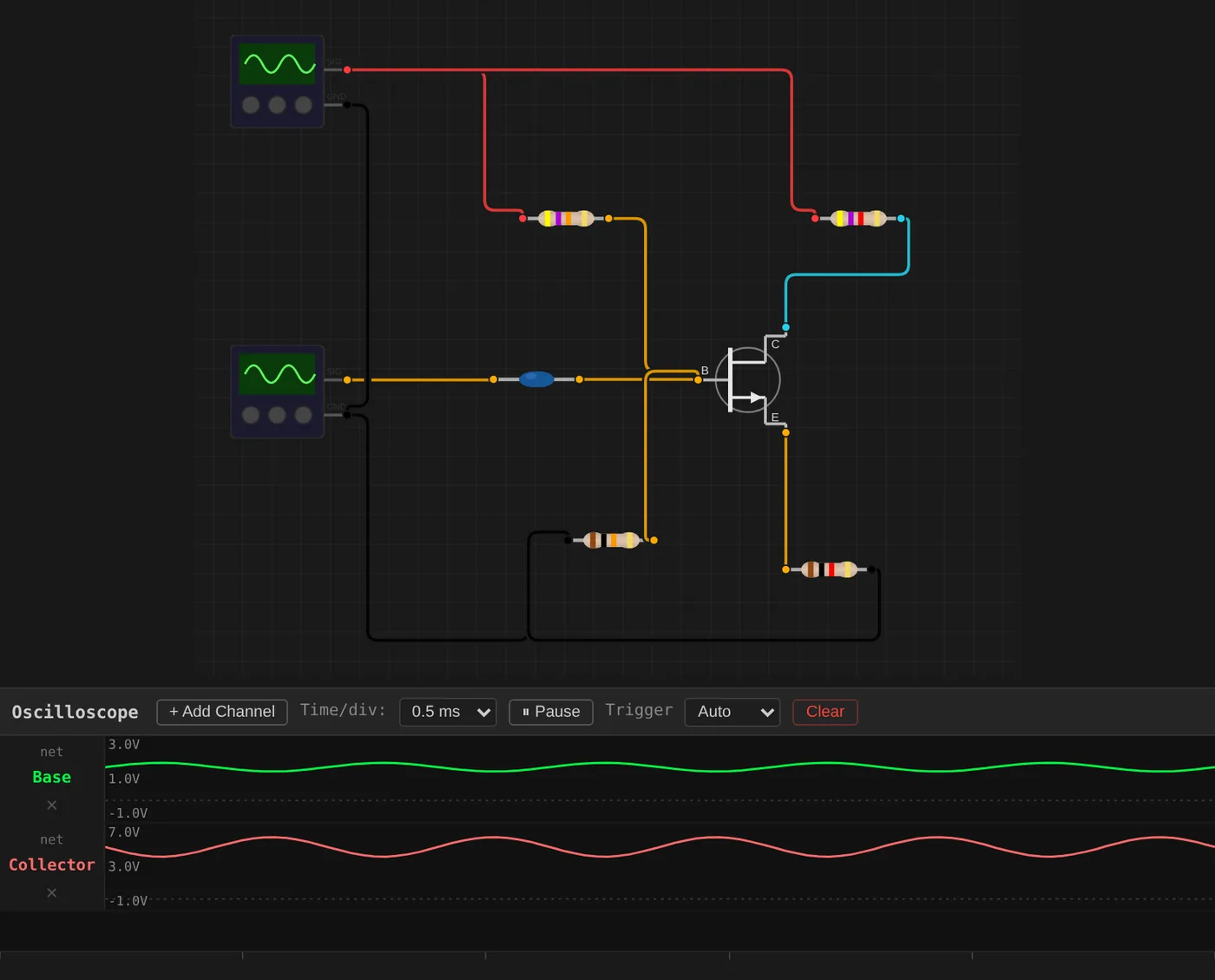
This is how a small signal becomes a big one: the common-emitter amplifier, the building block of every discrete audio amplifier. A 1 kHz sine of 0.4 V peak to peak enters through a coupling capacitor and comes out of the collector about four and a half times larger, and upside down. (The 9 V supply is the bench-supply symbol at the top left; the signal generator is below it.)
Two things make it work.
Bias. A transistor only amplifies when it is partly on. The 47 kΩ / 10 kΩ divider sets the base at 1.54 V. The emitter sits one diode drop lower, 0.89 V, so 0.89 mA flows through the 1 kΩ emitter resistor. The same current through the 4.7 kΩ collector resistor drops 4.2 V, leaving the collector at 4.83 V, near the middle of the supply, with room to swing both ways.
Gain. A change at the base appears almost unchanged at the emitter, so it changes the current by ΔV / Re. That current change flows through Rc and moves the collector by ΔV × Rc / Re, in the opposite direction. So the gain is −Rc/Re = −4.7. The simulator measures 4.54: the transistor adds a small internal emitter resistance of about 26 mV / Ie ≈ 29 Ω, and 4700 / 1029 = 4.57.
On the scope, the base (green) moves 0.4 V around 1.5 V and the collector (red) moves 1.8 V around 4.8 V, with its peaks where the base has its valleys.
Try it: right-click the signal generator and raise its amplitude to 1 V. The collector would need to swing 9 V, more than the supply allows, so the top of the wave flattens against 9 V and the bottom against saturation: clipping, the sound of an overdriven amplifier.
Open the common-emitter amplifier in Velxio
5. A thermostat with an op-amp comparator
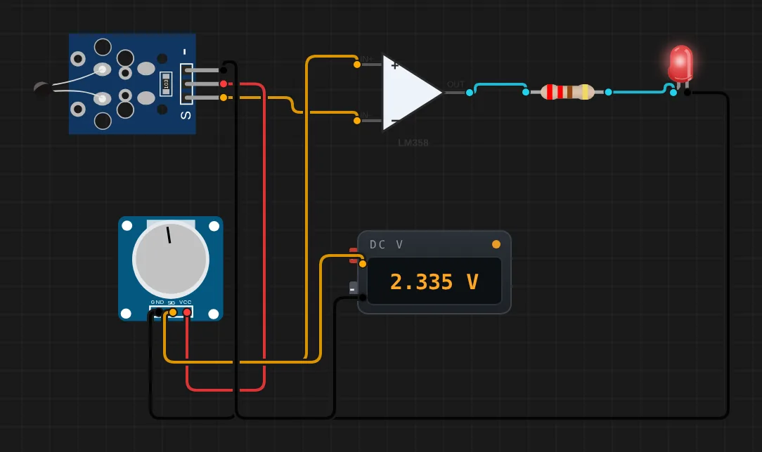
A thermostat that turns a fan on when it gets warm, using one LM358 op-amp and no code.
The sensor. The NTC thermistor’s resistance falls as it warms up (10 kΩ at 25 °C, about 7.4 kΩ at 32 °C). The module puts it under a fixed 10 kΩ resistor, so its output falls with temperature: 2.50 V at 25 °C, 2.12 V at 32 °C.
The set point. The potentiometer is a second divider. Its wiper sits at 2.336 V, the voltage the thermistor gives at 28 °C. The voltmeter shows it.
The comparator. An op-amp without feedback has so much gain that its output slams to one rail or the other depending on which input is higher. The set point goes to the + input and the thermistor to the − input: below 28 °C the thermistor’s voltage is higher and the output is at 0 V; above 28 °C it is lower and the output jumps to about 3.7 V, lighting the LED. At 27 °C the LED is off, at 29 °C it is on.
Why 3.7 V and not 5 V? The LM358 cannot drive its output all the way to its positive supply; it stops about 1.3 V short. Project 6 runs into the same limit.
A real thermostat adds hysteresis, so it does not chatter on and off while the temperature hovers at the threshold. Project 7 does that in code.
Try it: right-click the thermistor and change its temperature, or right-click the potentiometer and change its position (0 to 1023) to move the set point.
Open the op-amp thermostat in Velxio
6. Arduino: turning PWM into a real analog voltage
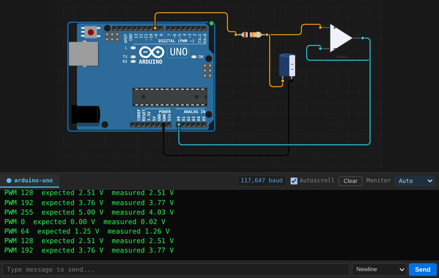
An Arduino Uno has no DAC: analogWrite() does not output a voltage, it outputs PWM, a 490 Hz square wave whose duty cycle sets the average. An LED or a motor does not care, but many circuits need a real, steady voltage. An analog filter makes one.
- RC low-pass filter. 10 kΩ and 10 µF average the PWM. Its time constant, τ = R·C = 0.1 s, is fifty times the PWM period, so the 490 Hz ripple is almost completely removed. The cost is speed: after a change the output takes about 5τ = 0.5 s to settle.
- Voltage follower. An LM358 with its output tied to its − input copies the filter’s voltage to its output. It draws almost no current from the filter, so whatever you connect next does not pull the voltage down.
- Feedback. A0 reads the result back, and the sketch prints what it asked for and what it got.
PWM 0    expected 0.00 V  measured 0.02 V
PWM 64   expected 1.25 V  measured 1.26 V
PWM 128  expected 2.51 V  measured 2.51 V
PWM 192  expected 3.76 V  measured 3.77 V
PWM 255  expected 5.00 V  measured 4.03 V
Up to 192 the DAC is accurate to 10 mV. At 255 it stops at 4.03 V: the filter does reach 5 V, but the LM358, powered from 5 V, cannot drive its output that high. The fix is a rail-to-rail op-amp such as the MCP6002, or to use only the range the LM358 can reach.
Open the Arduino PWM DAC in Velxio
7. ESP32: a thermometer that switches a fan
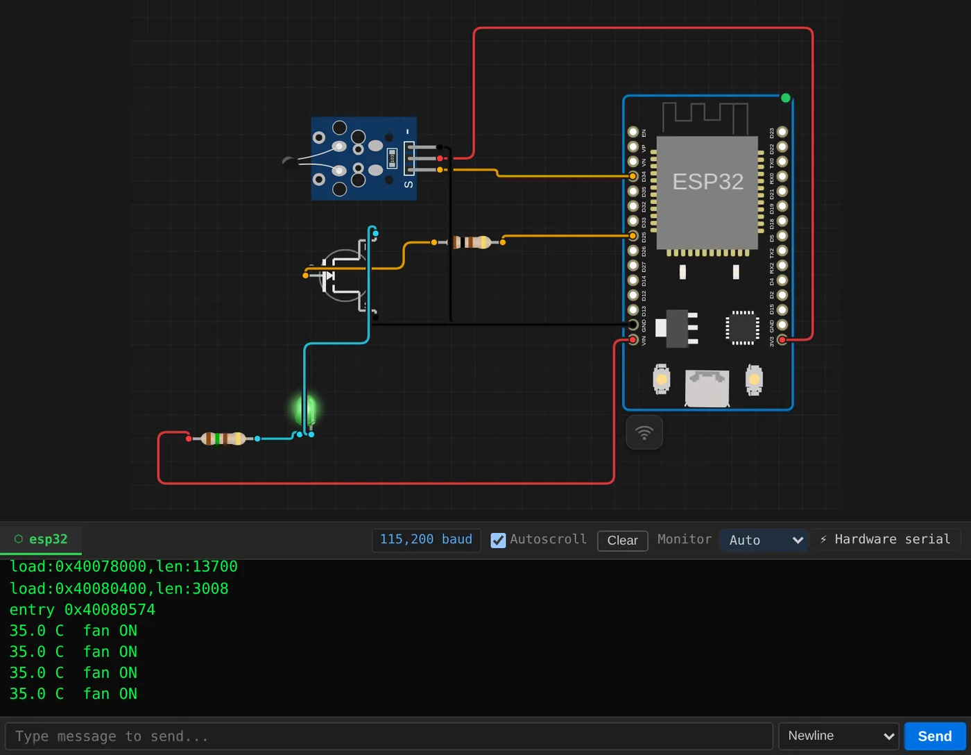
The thermostat again, this time with a microcontroller deciding, so it can do things a comparator cannot: show the temperature in degrees and add hysteresis.
Reading the temperature. The NTC module’s output goes to GPIO34, an input-only pin on the ESP32’s first ADC. The sketch averages 16 readings, works out the thermistor’s resistance from the divider (R = 10 kΩ × V / (3.3 V − V)), and converts it to degrees with the Beta equation from the thermistor’s datasheet: 1/T = 1/T₀ + ln(R/R₀)/β, with R₀ = 10 kΩ at T₀ = 25 °C and β = 3950. The serial monitor prints 25.0 °C when the thermistor is set to 25 °C, and 35.0 °C at 35 °C.
Switching the load. A GPIO pin can supply a few milliamps, not the hundreds a fan needs. GPIO25 drives the gate of a 2N7000 MOSFET instead, through a 100 Ω resistor, and the MOSFET connects the fan (a green LED here) to ground. At 35 °C the drain sits at 0.06 V: the MOSFET is fully on.
Hysteresis. The fan turns on at 30 °C and off only below 28 °C. Without that 2 °C gap, a temperature hovering at the threshold would switch the fan on and off every second.
For a real fan, use a logic-level MOSFET rated for the fan’s current (the 2N7000 is fine for small loads only) and a diode across the fan to absorb the motor’s voltage spike when it switches off.
Open the ESP32 thermometer and fan in Velxio
What we fixed while building these
Writing this article meant measuring every circuit, and the measurements turned up problems in the simulator, all fixed before publishing:
- After
analogWrite(pin, 0)oranalogWrite(pin, 255)following a PWM value, the circuit kept seeing the old PWM level. Project 6’s table caught it. - The voltmeter and ammeter averaged the power-on transient into their AC readings: the 7805’s output read 3.47 V instead of 5 V.
- The oscilloscope’s analog channels had a fixed ±4 V range, so a 5 V or 12 V signal was drawn off the screen. They now scale themselves.
- Voltage regulators did not draw any current from their input, so a power supply showed no ripple at all.
If you build an analog circuit in Velxio and the numbers do not match the formula, tell us on GitHub. That is how these were found.