Grove is Seeed Studio’s plug-and-play system: a four-pin connector, one cable, and a few hundred modules that share it. A button, a temperature sensor, a relay, an OLED, a thermal camera and a LoRa radio all plug into the same socket, which is why so many first projects are built on it.
As of September 2026, 222 of the 279 modules in Seeed’s Grove catalog run in Velxio. Each one has its own part on the canvas, drawn from the product photo, a datasheet card with the link to Seeed’s store, and a gallery example adapted from Seeed’s own wiki, wired to a XIAO board. This article walks through what that means in practice.
What a Grove module looks like on the canvas
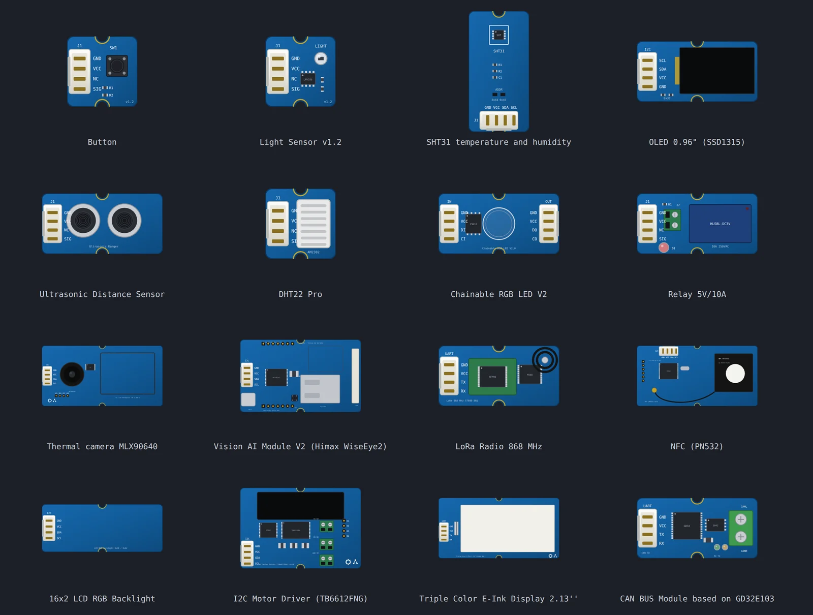
Every module is drawn from Seeed’s product photo, with the connector, the
parts and the silk where they are on the board, and it carries Seeed’s exact
product name. The pins are the connector’s four lines, named as the silk
names them, so a wire from SIG or SDA lands where it would on the bench.
What you get with each part:
- A datasheet card. Click the part and the dialog shows what the module is, which chip it carries, its I2C address where it has one, and a Product page button to Seeed’s store.
- The controls a real one would need. An analog sensor gets a slider for the quantity it measures. A button is clickable. A relay clicks and lights its LED. A display paints what the sketch sends. A radio gets a panel that plays the other end of the link.
- A gallery example. Each module ships with a sketch adapted from Seeed’s wiki, wired to a XIAO ESP32-C6, with the libraries the sketch needs already declared. Open it, press Run, and the module answers.
To find them, open the component picker and type “Grove”, or open the examples gallery and filter by Seeed Studio.
Try three of them
The steps are the same for every example:
- Open the example link. You do not need an account.
- Press the play button on the toolbar. The sketch compiles on Velxio’s servers and the board boots in your browser.
- Move the module’s sliders, click its buttons, or watch it draw.
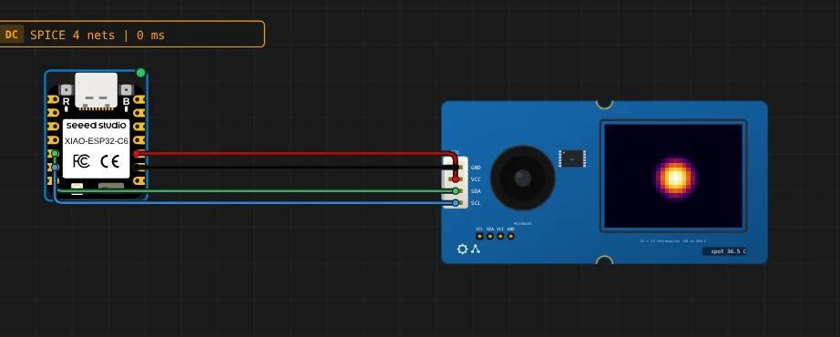
A thermal camera. The MLX90640 is a 32 by 24 array of thermopiles. The sketch pulls the sensor’s calibration EEPROM, reads a frame and runs Melexis’ own radiometric maths, and prints the frame to the serial monitor as ASCII art. The part shows the same frame as a heat map; the slider sets where the hot spot is and how warm.
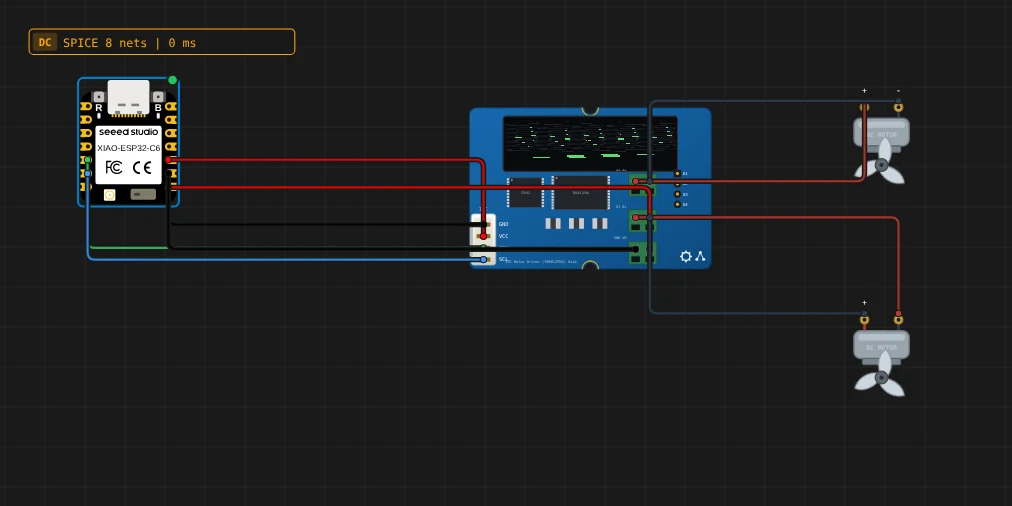
Two motors on one driver. The I2C Motor Driver carries a TB6612FNG behind a small STM32 that speaks a command protocol. The example runs two DC motors forward, reverse and brake; the rotors on the canvas turn at the commanded speed and direction, and brake locks them.
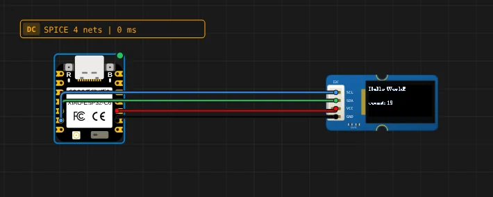
An OLED. The 0.96” SSD1315 is the display most Grove kits ship with. The example is Seeed’s u8g2 hello world: a line of text and a counter, sent over I2C at 0x3C, painted by a model of the controller.
How a module is emulated
Nothing here is faked at the library level. The sketch is compiled by a real
arduino-cli for the board you chose, the firmware runs on Velxio’s
emulator for that SoC, and the module answers on the wire the way the part
would. What differs from module to module is what “the wire” is:
- Analog modules (32 of them: light, sound, moisture, gas, current,
temperature) put a voltage on
SIG, set by the slider. The sketch reads it withanalogRead()through the board’s ADC model. - Digital inputs and outputs are a level on
SIG: buttons, switches, PIR and touch sensors on one side, LEDs, relays and buzzers on the other. - Pulse and timing modules such as the Ultrasonic Ranger and the DHT family use a line model: the edges are scheduled on the emulated CPU’s own clock, because a DHT22 frame is microseconds and a browser frame is sixteen milliseconds.
- NeoPixel and PWM modules decode the waveform the sketch produces.
- I2C, UART and SPI modules are the largest group: 84 modules on 78 device models written in C and compiled to WebAssembly. Each model answers the register reads and commands the vendor’s driver sends, and the same C source runs inside the browser and inside Velxio’s cloud emulators for the boards that run there.
The device models are short, because most parts follow one of a few shapes: a register map with an auto-incrementing pointer, a Sensirion-style command device with CRC-8 on every word, or a flat frame the sensor streams. The SHT31 model is the whole of Seeed’s temperature and humidity sensor, minus the comments:
static uint32_t handle(sn_dev* d, uint16_t cmd, const uint16_t* args, uint32_t nargs, uint16_t* w) {
  (void)d; (void)args; (void)nargs;
  switch (cmd) {
    case 0x306D: heater = true;  return 0;
    case 0x3066: heater = false; return 0;
    case 0x30A2: heater = false; return 0;   /* soft reset */
    case 0x3093: return 0;                    /* break */
    case 0x3041: return 0;                    /* clear status */
    case 0xF32D: {                            /* status register */
      uint16_t st = heater ? 0x2000 : 0x0000;
      w[0] = st; return 1;
    }
    default: break;
  }
  /* Everything else is a measurement request (single shot, periodic, fetch). */
  double t = vx_attr_read(A_temp) + (heater ? 2.0 : 0.0);
  double h = vx_attr_read(A_hum);
  w[0] = gc_u16((gc_clamp(t, -45, 130) + 45.0) * 65535.0 / 175.0);
  w[1] = gc_u16(gc_clamp(h, 0, 100) * 65535.0 / 100.0);
  return 2;
}
A_temp and A_hum are the two sliders. The conversion is the one in the
SHT31 datasheet, run backwards: the slider says 25 degrees, the model
produces the raw word the driver will turn back into 25 degrees, CRC and all.
Where the models come from
Each model is written against a document: the part’s datasheet, or the vendor library that talks to it, read line by line. When neither existed the module was left out rather than guessed. Three cases show what that meant.
The thermal cameras had to be derived, not transcribed. A thermal driver never reads a temperature. It pulls 832 words of EEPROM, extracts about two hundred calibration constants, reads 832 words of frame data and runs the manufacturer’s model. So the MLX90640 model serves a degenerate calibration in which every correction term vanishes, and works the maths backwards from the temperature the slider asks for to the raw word that produces it. It was checked against a port of the driver before any C was written; a target of -20 to 300 degrees round-trips to within 0.02 degrees. The MLX90641 needed the same trick plus a Hamming-coded EEPROM, and the MLX90621, which Seeed publishes nothing for, came from Melexis’ reference driver.
The motor driver example uses raw Wire. Seeed’s library for the
TB6612FNG board vendors an AVR-era I2C helper that does not compile for an
ESP32, so the example speaks the protocol directly. It is a command byte and
its payload:
const uint8_t ADDR = 0x14;
const uint8_t BRAKE = 0x00, CW = 0x02, CCW = 0x03;
const uint8_t STANDBY = 0x04, NOT_STANDBY = 0x05;
const uint8_t CHA = 0, CHB = 1;

void cmd(uint8_t c, const uint8_t* payload, uint8_t n) {
  Wire.beginTransmission(ADDR);
  Wire.write(c);
  for (uint8_t i = 0; i < n; i++) Wire.write(payload[i]);
  Wire.endTransmission();
  delay(1);
}

void run(uint8_t channel, int speed) {
  uint8_t p[2] = { channel, (uint8_t)(speed < 0 ? -speed : speed) };
  cmd(speed >= 0 ? CW : CCW, p, 2);
}
The CAN BUS module is not a Seeed design. It was first left out because
Seeed publishes no protocol and no library for it. The board is made by
Longan Labs, who publish both, and the model follows their frame layout:
0xAA, a length, a command, the payload and a MODBUS CRC.
Every model has a test that drives it the way its driver does, byte for byte: 1,804 of them across the catalog in September 2026. The gallery examples were also run on the deployed app, not only in the test suite.
What is not in the catalog
Being straight about the gaps: 57 of the 279 SKUs are not modelled, and three groups account for the ones that could be.
- The DMX512 module. The board is a line driver; the hard part is that no Arduino library produces a DMX frame on a XIAO the way the board expects.
- The 433 MHz Simple RF Link kit. Its sketches use VirtualWire, which is not in the Arduino library index, and the receiving half would need the module to generate a bit stream into the board rather than answer it.
- Three boards sold under the Grove name: the Grove Beginner Kit, the Arduino Sensor Kit Base and the GrovePi+. They are boards with a microcontroller rather than modules, and they need their own board definitions.
The rest are cables, mounting hardware and kits.
Where to go next
- The component picker: press Add Component on the canvas and type “Grove”. Each card is a module; the description says what it does.
- The examples gallery on velxio.dev/examples, filtered by Seeed Studio, has one example per module.
- The modules are on Seeed’s store under Grove; every part’s datasheet card links to its page.
Module art is drawn from Seeed Studio’s product photographs.