Arduino, running the sketch you wrote
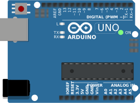
arduino-cli compiles it, an AVR8 core executes it instruction by instruction, and the LCD shows what the ATmega328P actually put on the bus. Uno, Nano, Mega and ATtiny85, no board on your desk.

Hardware is all about iteration. Velxio lets you wire a circuit, program the board and run it in seconds, real firmware on a real solver, right in the browser.





DFRobot · M5Stack links on this page are affiliate links: a purchase through them earns Velxio a small commission at no extra cost to you.
Nothing on this page is a scripted animation: the firmware is compiled and executed, and the circuit around it is solved.
arduino-cli compiles it, an AVR8 core executes it instruction by instruction, and the LCD shows what the ATmega328P actually put on the bus. Uno, Nano, Mega and ATtiny85, no board on your desk.
arduino-cli or ESP-IDF compiles the sketch, then AVR8, RP2040, RISC-V, Xtensa or ARM executes it instruction by instruction. What the OLED draws and what the serial monitor prints is what the chip actually did.

ngspice compiled to WebAssembly runs a full nodal analysis about 60 times a second. GPIO pins drive real nets, ADC inputs read solved node voltages, and probes report RMS, DC and current wherever you drop them.
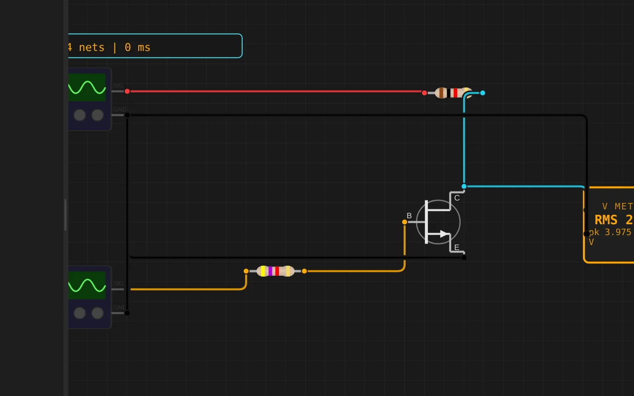
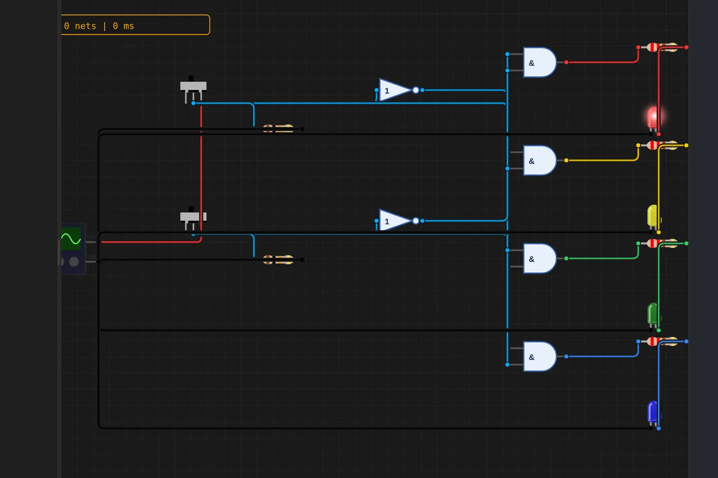
Adders, comparators, decoders, flip-flops and a 1-bit ALU slice: no microcontroller anywhere, just gates, switches and LEDs solved as a real net. The classroom half of electronics, without the breadboard.
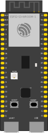
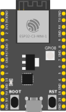
The M5Stack Cardputer with its keyboard, Seeed's round display keeping time, Pimoroni's Badger 2350 driving e-paper, and DFRobot's UNIHIKER M10 in the catalogue alongside them. Their makers sent the hardware so the emulation could be checked against the real thing.
35 boards across 6 CPU architectures — AVR8, ARM Cortex-M, ARM Cortex-A, RISC-V, Xtensa, and Linux. Including partner boards from Pimoroni, M5Stack, Seeed Studio and DFRobot. All running locally, no cloud needed.






One institution contract gives every student in the class a full Pro account. No per-seat checkout, no card details in a classroom.
Private projects, BOM and schematic exports and GitHub Sync, for everyone enrolled.
Billed once to your institution, per semester or per year. Volume pricing on request for large cohorts.
Arduino, ESP32, RP2040, STM32, ATtiny and Raspberry Pi, with SPICE analog solved alongside the firmware. Not a sandboxed mock.
The simulator stays free forever, WiFi with internet included. Paid plans unlock the Linux and STM32 boards, custom WiFi networks and the local network gateway. Maker and Pro add the AI agent; No AI leaves it out.
Discover the simulator + light AI help.
The full workbench, zero AI. You write every line.
For makers shipping real circuits with AI help.
Private projects, GitHub Sync and BOM exports.
Questions, bugs and ideas: the Discord and the issue tracker are open, and so is every line of the simulator.
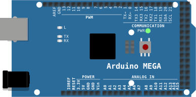
An interactive Arduino Mega circuit simulation you can run free in your browser on Velxio, by 25040118.
/*
 * 婴儿护理系统 (Baby Care System)
 * 平台: Arduino Mega 2560
 *
 * 接线:
 *   SSD1306 OLED (I2C) : GND->GND, VCC->5V, SDA->D20, SCL->D21 (地址 0x3C)
 *   DHT22              : VCC->5V, GND->GND, SDA->D2 (建议 DATA 加 10k 上拉)
 *   HC-SR04            : VCC->5V, GND->GND, TRIG->D3, ECHO->D4
 *   光敏电阻模块        : VCC->5V, GND->GND, AO->A0, DO->D5(未使用)
 *   Grove RGB LED      : GND->GND, VCC->5V, SIG->D6
 *   Grove RGB LED Ring : GND->GND, VCC->外部5V(24 灯建议), SIG->D10 (氛围灯)
 *   Grove 蜂鸣器        : GND->GND, VCC->5V, SIG->D8
 *   舵机               : V+->外部5V, GND->GND, PWM->D9
 *   L293D + 直流风扇    : EN1->D11(PWM), IN1->D7, IN2->D12,
 *                         OUT1/OUT2->风扇, VCC1->5V, VCC2->外部电源, GND 全接
 *   Grove MOSFET + 加热块: SIG->D13, VCC->5V, GND->GND, VIN±->外部电源, OUT±->加热块
 *   4x4 薄膜键盘        : 行 R1-R4->D22/D24/D26/D28, 列 C1-C4->D30/D32/D34/D36
 *   AD8232 心率         : VCC->5V, GND->GND, AOUT->A1
 *   声音传感器           : VCC->5V, GND->GND, AOUT->A2, DOUT 不接 (哭声检测)
 *   MPU6050            : VCC->5V, GND->GND, SDA->D20, SCL->D21, AD0->GND, INT/XDA/XCL 悬空
 *   OLED 屏1(传感器)   : SSD1306 4 针 I2C, 地址 0x3C, SCL->D21, SDA->D20, VCC->5V
 *   OLED 屏2(状态/报警) : SSD1306 4 针 I2C, 地址 0x3D, 与屏1 并联同一组 SCL/SDA
 *
 * 注: 风扇 EN1 不能放 D10。蜂鸣器 tone() 占用 Timer2,而 D9/D10 也是 Timer2,
 *     PWM 会被 tone 打乱;D11 属 Timer1,与 tone、Servo 都不冲突。
 *
 * 功能:
 *   温度 >= 30C -> 风扇 3 档    >= 28C -> 2 档    >= 26C -> 1 档
 *   温度 <= 24C -> 关风扇, 开加热块;  24-26C 之间风扇与加热都关
 *   超声波 45cm 内判定婴儿在床; 否则 OLED 显示 NOT FOUND, 且风扇/加热都停用
 *   环境光分 3 档: 越暗灯越亮, 足够亮时关灯
 *   蜂鸣器 = 循环播放音乐(小星星), 非阻塞
 *   舵机 = 上电不动作, 按 1 开始 0-90 度缓慢往复, 再按 1 停止并回 0 度
 *   蜂鸣器与舵机全程手动, 自动模式不会动它们, 且自动模式下也能按键控制
 *   哭声检测: 声音模块每 10ms 采样, 200ms 窗口强度 >= 阈值并持续 2s 判定哭闹,
 *             安静 2s 后解除; 哭闹只触发安抚与屏显, 不鸣蜂鸣器报警
 *   氛围灯(24 灯 WS2813 环): 待机暖色呼吸; 放音乐时随每个音符整圈换色;
 *             仅心率丢失报警时整圈全白
 *   安抚: 检测到哭声(且在床)自动启动 舵机往复 + 安抚音乐 + 氛围灯, 哭声消失即停;
 *         也可按 6 手动随时开关, 按 C/1/2 可立即关闭
 *   报警: 屏1/屏2 各状态行最右侧反白显示报警标签(仅显示, 不鸣响)
 *         温度行 HOT / COLD / WET, 在位行 OUT, 光照行 DARK, 声音行 CRY / MOVE,
 *         心率行 LOST
 *         报警码 A1 心率丢失 A2 离床 A3 哭闹 A4 过热 A5 过冷
 *                A6 湿度过高 A7 过暗 A8 动作
 *   A1 是唯一会启动"声光报警"的报警(蜂鸣器 + 灯圈全白 + 屏2 整屏反白):
 *         婴儿在床但 5s 收不到心电/心跳时触发; 其余报警只上屏
 *
 * 按键:
 *   A = 自动模式(执行传感器逻辑)
 *   B = 手动模式(关闭自动)
 *   C = 关闭所有设备并进入手动
 *   1 = 舵机往复 开/停          (自动/手动都可用)
 *   2 = 音乐 开/停              (自动/手动都可用)
 *   3 = 风扇档位循环 0->1->2->3->0   (仅手动)
 *   4 = 加热块开/关(与风扇互斥)      (仅手动)
 *   5 = 灯光档位循环 0->1->2->3->0   (仅手动)
 *   6 = 安抚模式 开/停: 舵机 + 安抚音乐 + 氛围灯一起启动
 *   6-9 预留
 *
 * 依赖库: Adafruit SSD1306 / Adafruit GFX / DHT sensor library (+ Unified Sensor)
 *         Servo / Keypad / Adafruit NeoPixel
 */

#include <Wire.h>
#include <Adafruit_GFX.h>
#include <Adafruit_SSD1306.h>
#include <DHT.h>
#include <Servo.h>
#include <Keypad.h>
#include <Adafruit_NeoPixel.h>

/* ---------------- 引脚 ---------------- */
const uint8_t PIN_DHT     = 2;
const uint8_t PIN_TRIG    = 3;
const uint8_t PIN_ECHO    = 4;
const uint8_t PIN_LDR_AO  = A0;
const uint8_t PIN_LDR_D