Arduino, running the sketch you wrote
arduino-cli compiles it, an AVR8 core executes it instruction by instruction, and the LCD shows what the ATmega328P actually put on the bus. Uno, Nano, Mega and ATtiny85, no board on your desk.

Hardware is all about iteration. Velxio lets you wire a circuit, program the board and run it in seconds, real firmware on a real solver, right in the browser.





DFRobot · M5Stack links on this page are affiliate links: a purchase through them earns Velxio a small commission at no extra cost to you.
Nothing on this page is a scripted animation: the firmware is compiled and executed, and the circuit around it is solved.
arduino-cli compiles it, an AVR8 core executes it instruction by instruction, and the LCD shows what the ATmega328P actually put on the bus. Uno, Nano, Mega and ATtiny85, no board on your desk.
arduino-cli or ESP-IDF compiles the sketch, then AVR8, RP2040, RISC-V, Xtensa or ARM executes it instruction by instruction. What the OLED draws and what the serial monitor prints is what the chip actually did.

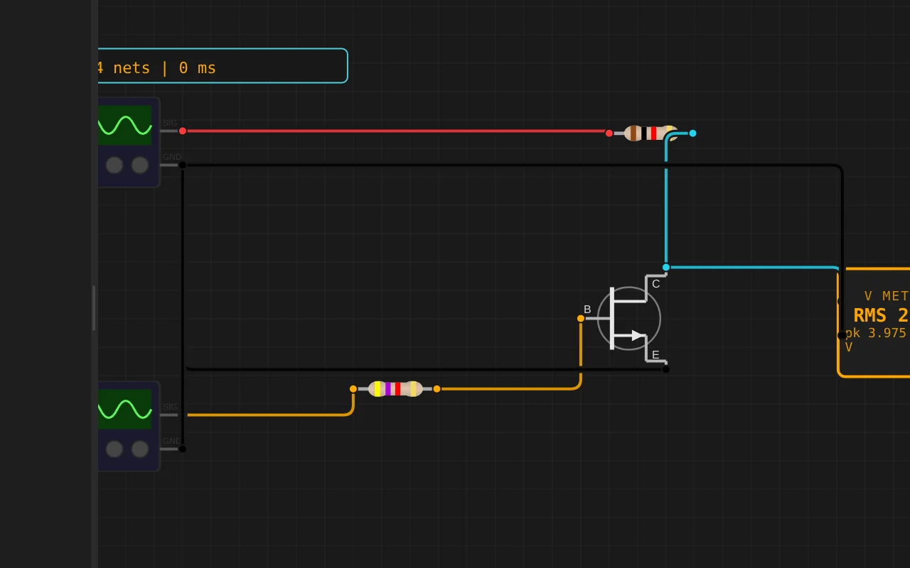
ngspice compiled to WebAssembly runs a full nodal analysis about 60 times a second. GPIO pins drive real nets, ADC inputs read solved node voltages, and probes report RMS, DC and current wherever you drop them.
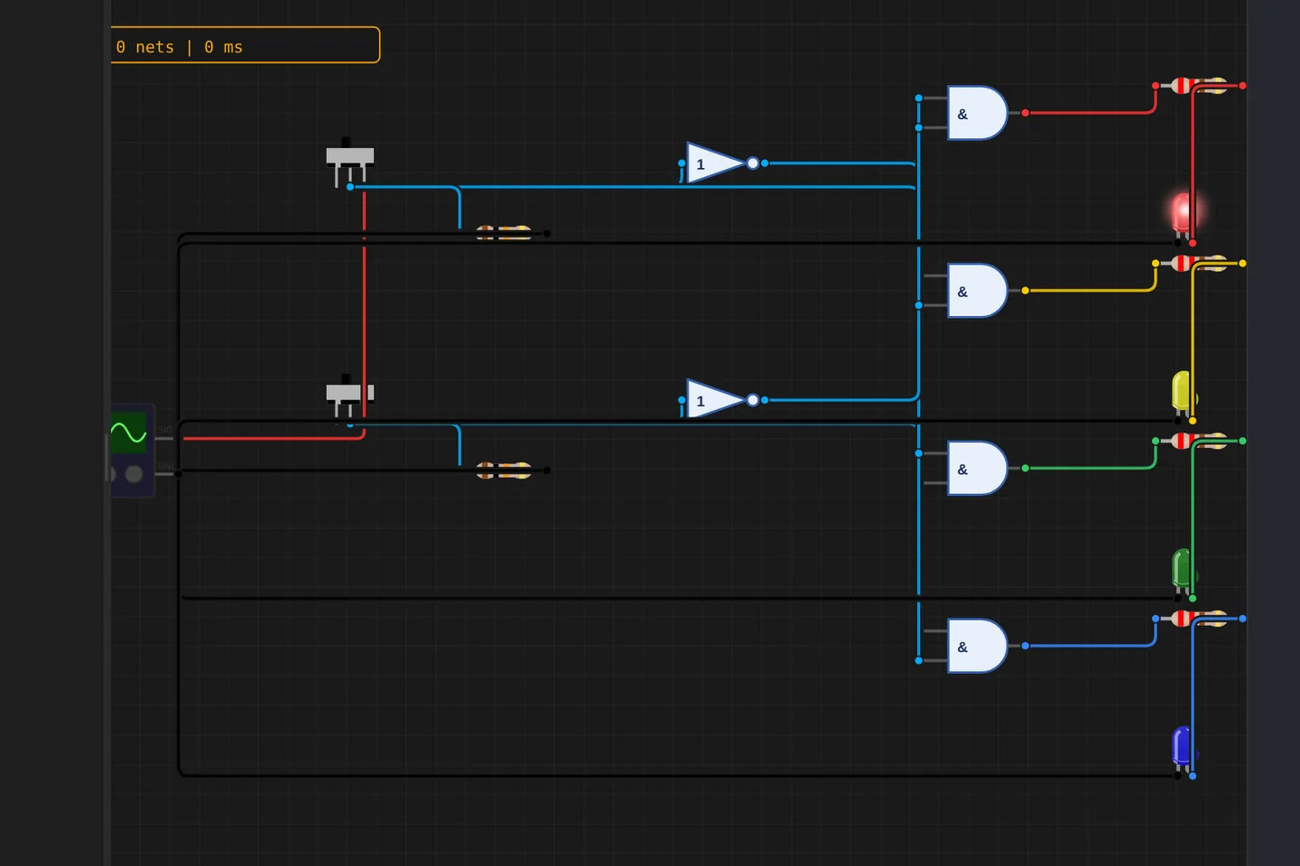
Adders, comparators, decoders, flip-flops and a 1-bit ALU slice: no microcontroller anywhere, just gates, switches and LEDs solved as a real net. The classroom half of electronics, without the breadboard.
The M5Stack Cardputer with its keyboard, Seeed's round display keeping time, Pimoroni's Badger 2350 driving e-paper, and DFRobot's UNIHIKER M10 in the catalogue alongside them. Their makers sent the hardware so the emulation could be checked against the real thing.
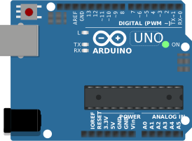
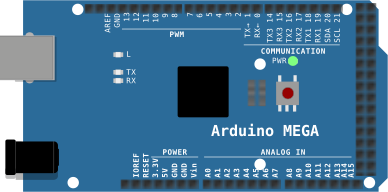
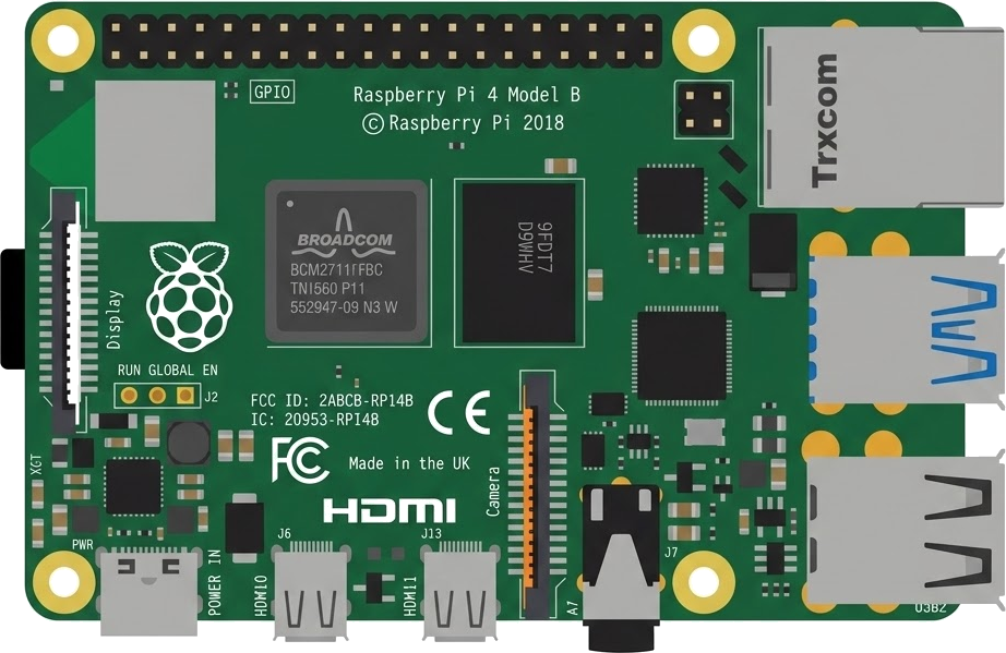
35 boards across 6 CPU architectures — AVR8, ARM Cortex-M, ARM Cortex-A, RISC-V, Xtensa, and Linux. Including partner boards from Pimoroni, M5Stack, Seeed Studio and DFRobot. All running locally, no cloud needed.






One institution contract gives every student in the class a full Pro account. No per-seat checkout, no card details in a classroom.
Private projects, BOM and schematic exports and GitHub Sync, for everyone enrolled.
Billed once to your institution, per semester or per year. Volume pricing on request for large cohorts.
Arduino, ESP32, RP2040, STM32, ATtiny and Raspberry Pi, with SPICE analog solved alongside the firmware. Not a sandboxed mock.
The simulator stays free forever, WiFi with internet included. Paid plans unlock the Linux and STM32 boards, custom WiFi networks and the local network gateway. Maker and Pro add the AI agent; No AI leaves it out.
Discover the simulator + light AI help.
The full workbench, zero AI. You write every line.
For makers shipping real circuits with AI help.
Private projects, GitHub Sync and BOM exports.
Questions, bugs and ideas: the Discord and the issue tracker are open, and so is every line of the simulator.
An interactive ESP32-S3 circuit simulation you can run free in your browser on Velxio, by janvelxio.
#include <SPI.h>
#include <Adafruit_GFX.h>
#include <Adafruit_ILI9341.h>

// ==========================================
// 🌟 模式开关:
// 1 = 模拟器模式(内部生成波形,避免模拟器ADC读取不到信号)
// 0 = 真实硬件模式(通过 GPIO 1 读取真实电压)
#define SIMULATOR_MODE 0
// ==========================================

#define TFT_SCK  12
#define TFT_MISO 13
#define TFT_MOSI 11
#define TFT_CS   10
#define TFT_DC    9
#define TFT_RST   8
#define ADC_PIN   1   // 仅真实硬件模式下有效

Adafruit_ILI9341 tft = Adafruit_ILI9341(TFT_CS, TFT_DC, TFT_RST);

#define SCREEN_WIDTH  320
#define SCREEN_HEIGHT 240
#define BUFFER_SIZE   320  // 采样点数

uint16_t adcBuffer[BUFFER_SIZE];
int prevY[SCREEN_WIDTH];     // 存储上一帧的Y坐标,用于擦除旧线
float phase = 0.0;           // 模拟器模式下的相位

void setup() {
  Serial.begin(115200);
  SPI.begin(TFT_SCK, TFT_MISO, TFT_MOSI, TFT_CS);
  tft.begin();
  tft.setRotation(3); // 根据你屏幕的方向调整,1或3

  tft.fillScreen(ILI9341_BLACK);
  drawGrid(); // 只在开机时画一次网格,之后绝对不碰网格

  // 初始化上一帧坐标
  for (int i = 0; i < SCREEN_WIDTH; i++) {
    prevY[i] = SCREEN_HEIGHT / 2;
  }
}

void loop() {
  // ---------------- 1. 采集数据 ----------------
  if (SIMULATOR_MODE) {
    // 【模拟器模式】用数学公式生成 50Hz 正弦波(对应0~2V的ADC值)
    for (int i = 0; i < BUFFER_SIZE; i++) {
      adcBuffer[i] = 1240 + 1240 * sin(phase + i * 0.05);
    }
    phase += 0.15; // 产生动态滚动效果
  } else {
    // 【真实硬件模式】带“触发”机制的ADC采样
    // 真实示波器不滚动的秘诀:等待电压上升到特定阈值时,才开始记录这320个点
    bool triggered = false;
    unsigned long timeout = millis();

    while (!triggered && (millis() - timeout < 100)) {
      int val = analogRead(ADC_PIN);
      // 触发条件:电压从低于1V(ADC约1240)上升到高于1V
      if (val > 1240) {
         // 再确认一次确实是上升沿
         if (analogRead(ADC_PIN) > 1240) {
            triggered = true;
         }
      }
    }
    // 捕获数据
    for (int i = 0; i < BUFFER_SIZE; i++) {
      adcBuffer[i] = analogRead(ADC_PIN);
    }
  }

  // ---------------- 2. 绘制波形(擦除+画新线) ----------------
  int x0 = 0;
  // 映射第一点 (0~4095 -> 屏幕Y轴,留出上下40像素边距)
  int y0 = map(adcBuffer[0], 0, 4095, SCREEN_HEIGHT - 40, 40);
  if (y0 < 0) y0 = 0; if (y0 > SCREEN_HEIGHT - 1) y0 = SCREEN_HEIGHT - 1;

  for (int x = 1; x < BUFFER_SIZE; x++) {
    int y = map(adcBuffer[x], 0, 4095, SCREEN_HEIGHT - 40, 40);
    if (y < 0) y = 0; if (y > SCREEN_HEIGHT - 1) y = SCREEN_HEIGHT - 1;

    // 2.1 用黑色擦除上一帧的线 (避免闪烁)
    tft.drawLine(x0, prevY[x0], x, prevY[x], ILI9341_BLACK);

    // 2.2 画新线
    tft.drawLine(x0, y0, x, y, ILI9341_GREEN);

    // 记录当前坐标为下一帧的“旧坐标”
    prevY[x0] = y0;
    y0 = y;
    x0 = x;
  }
  prevY[x0] = y0; // 记录最后一点

  delay(20); // 控制刷新率,防止模拟器卡顿,真实硬件可以调小到 5-10
}

// 画网格函数
void drawGrid() {
  for (int x = 0; x < SCREEN_WIDTH; x += SCREEN_WIDTH / 10) {
    tft.drawFastVLine(x, 0, SCREEN_HEIGHT, 0x4208);
  }
  for (int y = 0; y < SCREEN_HEIGHT; y += SCREEN_HEIGHT / 8) {
    tft.drawFastHLine(0, y, SCREEN_WIDTH, 0x4208);
  }
  tft.drawFastHLine(0, SCREEN_HEIGHT / 2, SCREEN_WIDTH, 0x4208);
  tft.drawFastVLine(SCREEN_WIDTH / 2, 0, SCREEN_HEIGHT, 0x4208);
}