Arduino, running the sketch you wrote
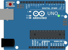
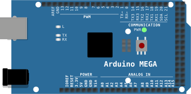
arduino-cli compiles it, an AVR8 core executes it instruction by instruction, and the LCD shows what the ATmega328P actually put on the bus. Uno, Nano, Mega and ATtiny85, no board on your desk.

Hardware is all about iteration. Velxio lets you wire a circuit, program the board and run it in seconds, real firmware on a real solver, right in the browser.





DFRobot · M5Stack links on this page are affiliate links: a purchase through them earns Velxio a small commission at no extra cost to you.
Nothing on this page is a scripted animation: the firmware is compiled and executed, and the circuit around it is solved.
arduino-cli compiles it, an AVR8 core executes it instruction by instruction, and the LCD shows what the ATmega328P actually put on the bus. Uno, Nano, Mega and ATtiny85, no board on your desk.
arduino-cli or ESP-IDF compiles the sketch, then AVR8, RP2040, RISC-V, Xtensa or ARM executes it instruction by instruction. What the OLED draws and what the serial monitor prints is what the chip actually did.

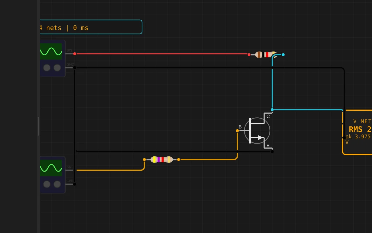
ngspice compiled to WebAssembly runs a full nodal analysis about 60 times a second. GPIO pins drive real nets, ADC inputs read solved node voltages, and probes report RMS, DC and current wherever you drop them.
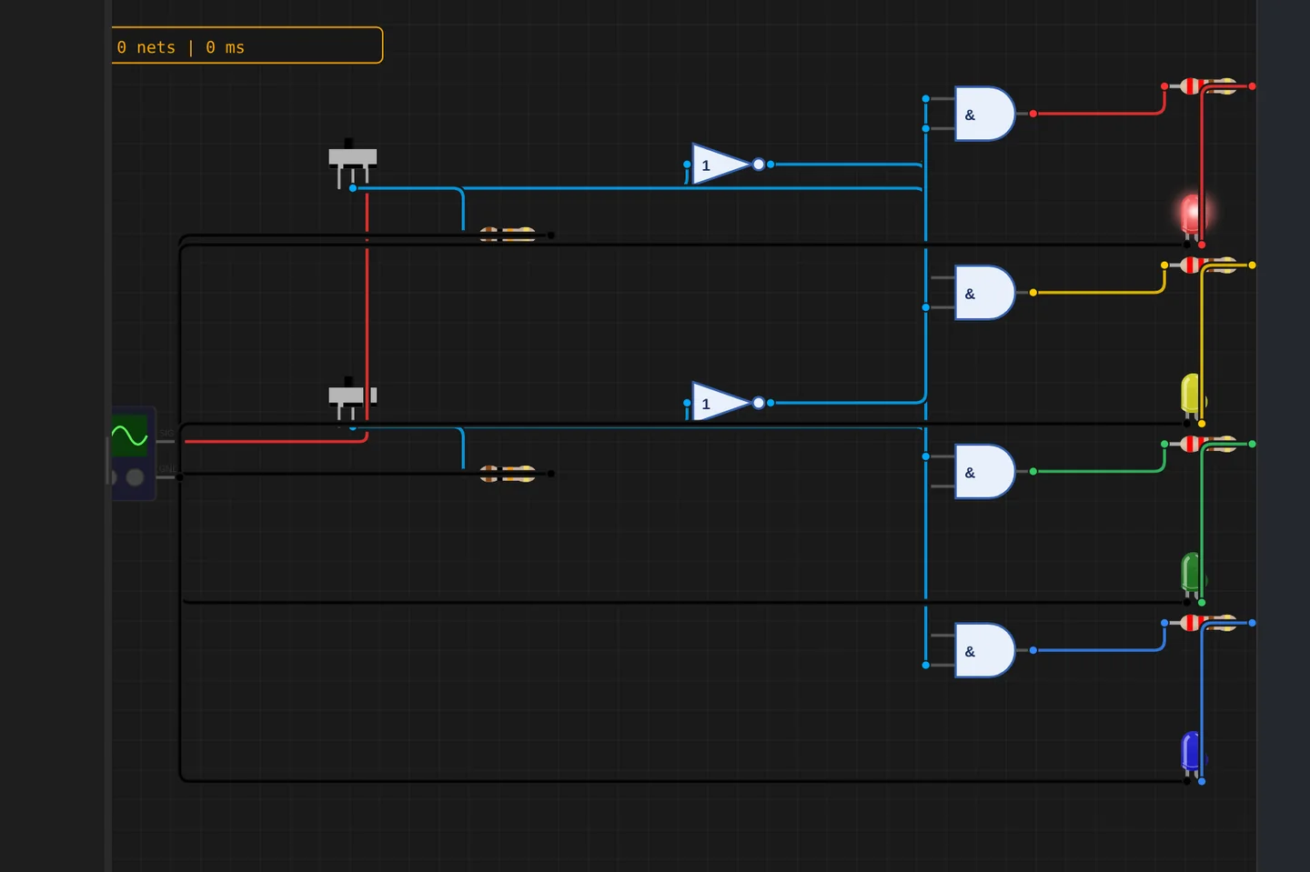
Adders, comparators, decoders, flip-flops and a 1-bit ALU slice: no microcontroller anywhere, just gates, switches and LEDs solved as a real net. The classroom half of electronics, without the breadboard.
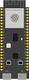
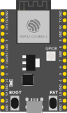
The M5Stack Cardputer with its keyboard, Seeed's round display keeping time, Pimoroni's Badger 2350 driving e-paper, and DFRobot's UNIHIKER M10 in the catalogue alongside them. Their makers sent the hardware so the emulation could be checked against the real thing.
35 boards across 6 CPU architectures — AVR8, ARM Cortex-M, ARM Cortex-A, RISC-V, Xtensa, and Linux. Including partner boards from Pimoroni, M5Stack, Seeed Studio and DFRobot. All running locally, no cloud needed.






One institution contract gives every student in the class a full Pro account. No per-seat checkout, no card details in a classroom.
Private projects, BOM and schematic exports, GitHub Sync and the offline desktop app, for everyone enrolled.
Billed once to your institution, per semester or per year. Volume pricing on request for large cohorts.
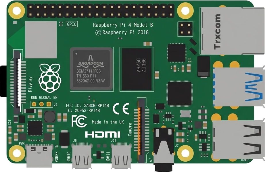
Arduino, ESP32, RP2040, STM32, ATtiny and Raspberry Pi, with SPICE analog solved alongside the firmware. Not a sandboxed mock.
The simulator stays free forever. Paid plans unlock the Linux and STM32 boards, WiFi and the offline desktop app. Maker and Pro add the AI agent; No AI leaves it out.
Discover the simulator + light AI help.
The full workbench, zero AI. You write every line.
For makers shipping real circuits with AI help.
Private projects, GitHub Sync and BOM exports.
Questions, bugs and ideas: the Discord and the issue tracker are open, and so is every line of the simulator.
ESP32 with SSD1306 OLED showing WiFi connection status and IP address
An interactive ESP32 circuit simulation you can run free in your browser on Velxio, by ericcraft-mail.
#include <Wire.h>
#include <WiFi.h>
#include <SPI.h>
#include <Adafruit_GFX.h>
#include <Adafruit_SSD1306.h>

#define SCREEN_WIDTH 128
#define SCREEN_HEIGHT 64

// Define SPI pins based on the wiring above
#define OLED_MOSI   23
#define OLED_CLK    18
#define OLED_DC      2
#define OLED_CS      5
#define OLED_RESET   4

// Declaration for SSD1306 display connected using software SPI
Adafruit_SSD1306 display(SCREEN_WIDTH, SCREEN_HEIGHT, OLED_MOSI, OLED_CLK, OLED_DC, OLED_RESET, OLED_CS);

const char* ssid = "RUT_F2CE_2G"; //RUT_F2CE_2G Espressif
const char* pwd  = "n9E5WjMf"; // n9E5WjMf

//display.drawBitmap(112, 0, cell_no_signal_16x8, 16, 8, SSD1306_WHITE);
// const unsigned char cell_no_signal_16x8[] = {
//   0x00, 0x00, 0x04, 0x10, 0x02, 0x20, 0x01, 0x40, 0x00, 0x80, 0x01, 0x40, 0x02, 0x20, 0x04, 0x10
// };

// Draw 4-bar signal strength icon at (x, y), each bar 3px wide, 2px gap
// Bars grow upward: bar0 is shortest (left), bar3 is tallest (right)
void drawSignalIcon(int x, int y, int8_t rssi) {
  const int barWidth  = 2;
  const int gap       = 1;
  const int maxHeight = 10;
  const int minBar    = 1; // minimum bar height so even bar0 is visible

  // Map RSSI (-90..-30) to signal level (0..4 bars)
  int level;
  if (rssi >= -40)      level = 5; // excellent
  else if (rssi >= -50) level = 4; // good
  else if (rssi >= -60) level = 3; // good
  else if (rssi >= -70) level = 2; // fair
  else if (rssi >= -80) level = 1; // weak
  else                  level = 0; // no signal

  for (int i = 0; i < 5; i++) {
    // Bar heights: 2, 4, 6, 8 pixels
    int barH = minBar + (maxHeight - minBar) * (i + 1) / 5;
    // x position for this bar (left to right, shortest to tallest)
    int bx = x + i * (barWidth + gap);

    // Draw bar outline (full height)
    //display.drawRect(bx, y + maxHeight - barH, barWidth, barH, SSD1306_WHITE);

    // Fill only if this bar is within the active level
    if (i < level) {
      display.fillRect(bx, y + maxHeight - barH, barWidth, barH, SSD1306_WHITE);
    }
  }
}

// Draw times icon procedural starting at x and y position, size of image drawn (size = 8x8)
void drawTimesIcon(int8_t x, int8_t y, int8_t size){
  // Get the last y coords to draw backward
  int yH = y + size - 1; // 16 + 8 - 1 = 23

  for (int i = 0; i < size; i++) {
    display.drawPixel(x + i, y + i, SSD1306_WHITE);
    display.drawPixel(x + i, yH - i, SSD1306_WHITE);
  }
}

void setup() {
  Serial.begin(115200);
  //Wire.begin(21, 22);
  if (!display.begin(SSD1306_SWITCHCAPVCC, 0x3C)) {
    Serial.println("SSD1306 not found!");
    while (true) delay(10);
  }

  display.clearDisplay();
  display.setTextColor(SSD1306_WHITE);
  display.setCursor(0, 20);
  display.printf("Connecting to SSID:\n%s", ssid);

  WiFi.begin(ssid, pwd);  // channel 6, no password

  while (WiFi.status() != WL_CONNECTED) {
    delay(500);
    Serial.print(".");
    display.print(".");
    display.display();
  }

  Serial.println("Connected!");
}

void loop() {
  display.cl