Arduino, running the sketch you wrote
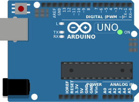
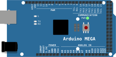
arduino-cli compiles it, an AVR8 core executes it instruction by instruction, and the LCD shows what the ATmega328P actually put on the bus. Uno, Nano, Mega and ATtiny85, no board on your desk.

Hardware is all about iteration. Velxio lets you wire a circuit, program the board and run it in seconds, real firmware on a real solver, right in the browser.





DFRobot · M5Stack links on this page are affiliate links: a purchase through them earns Velxio a small commission at no extra cost to you.
Nothing on this page is a scripted animation: the firmware is compiled and executed, and the circuit around it is solved.
arduino-cli compiles it, an AVR8 core executes it instruction by instruction, and the LCD shows what the ATmega328P actually put on the bus. Uno, Nano, Mega and ATtiny85, no board on your desk.
arduino-cli or ESP-IDF compiles the sketch, then AVR8, RP2040, RISC-V, Xtensa or ARM executes it instruction by instruction. What the OLED draws and what the serial monitor prints is what the chip actually did.

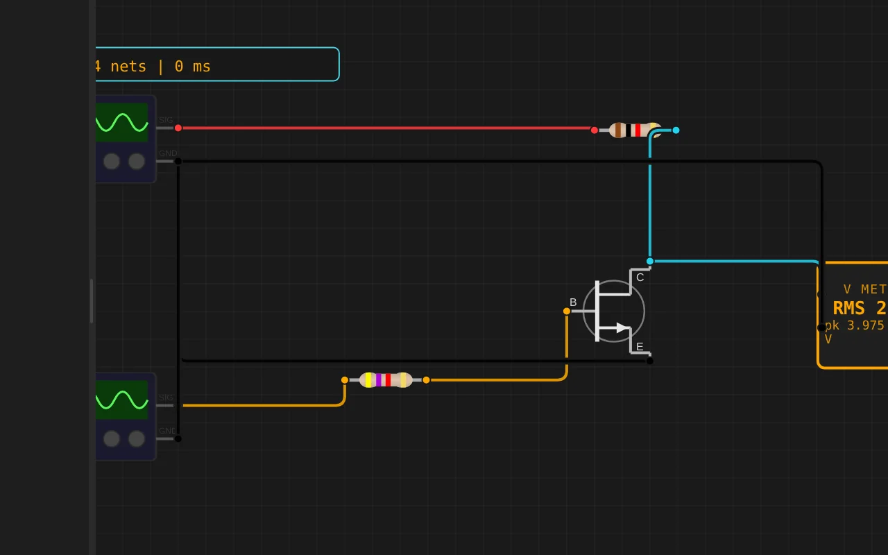
ngspice compiled to WebAssembly runs a full nodal analysis about 60 times a second. GPIO pins drive real nets, ADC inputs read solved node voltages, and probes report RMS, DC and current wherever you drop them.
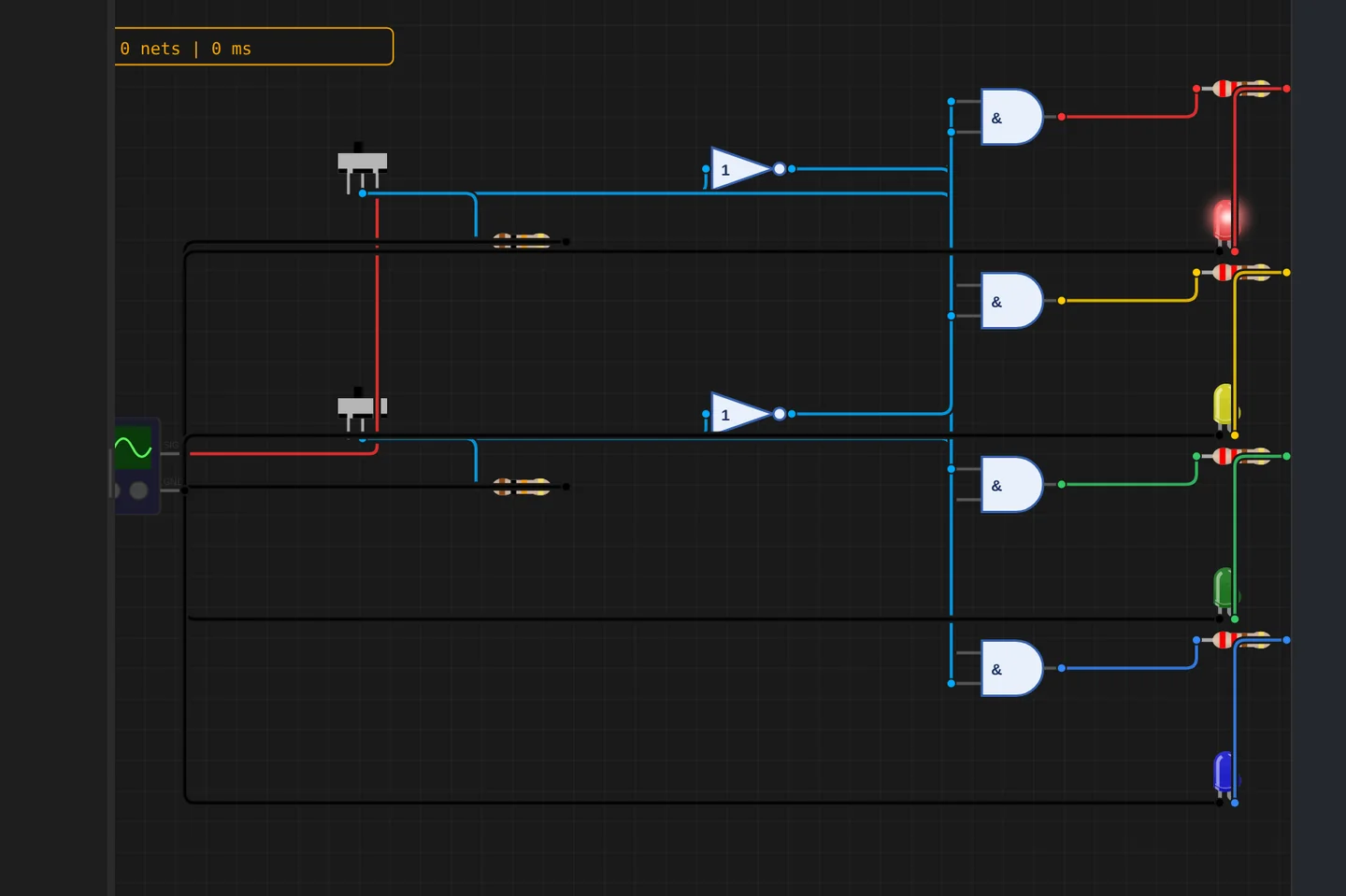
Adders, comparators, decoders, flip-flops and a 1-bit ALU slice: no microcontroller anywhere, just gates, switches and LEDs solved as a real net. The classroom half of electronics, without the breadboard.
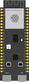
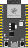
The M5Stack Cardputer with its keyboard, Seeed's round display keeping time, Pimoroni's Badger 2350 driving e-paper, and DFRobot's UNIHIKER M10 in the catalogue alongside them. Their makers sent the hardware so the emulation could be checked against the real thing.
35 boards across 6 CPU architectures — AVR8, ARM Cortex-M, ARM Cortex-A, RISC-V, Xtensa, and Linux. Including partner boards from Pimoroni, M5Stack, Seeed Studio and DFRobot. All running locally, no cloud needed.






One institution contract gives every student in the class a full Pro account. No per-seat checkout, no card details in a classroom.
Private projects, BOM and schematic exports, GitHub Sync and the offline desktop app, for everyone enrolled.
Billed once to your institution, per semester or per year. Volume pricing on request for large cohorts.
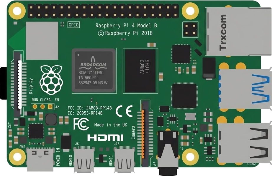
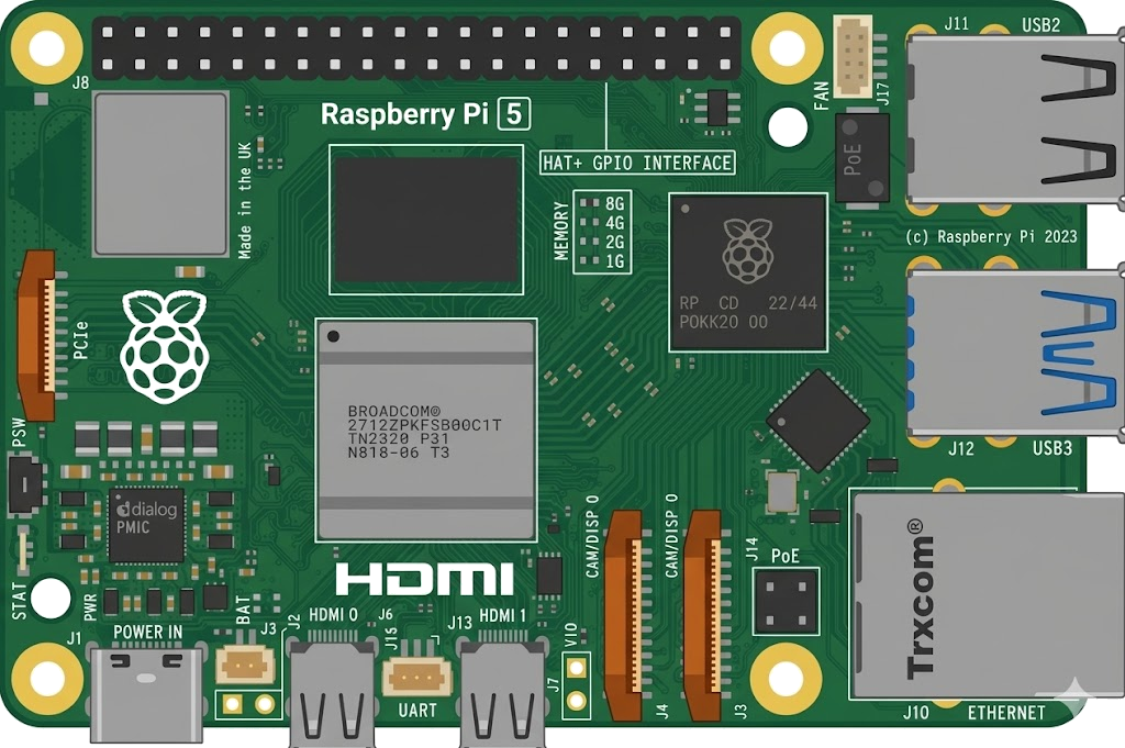
Arduino, ESP32, RP2040, STM32, ATtiny and Raspberry Pi, with SPICE analog solved alongside the firmware. Not a sandboxed mock.
The simulator stays free forever. Paid plans unlock the Linux and STM32 boards, WiFi and the offline desktop app. Maker and Pro add the AI agent; No AI leaves it out.
Discover the simulator + light AI help.
The full workbench, zero AI. You write every line.
For makers shipping real circuits with AI help.
Private projects, GitHub Sync and BOM exports.
Questions, bugs and ideas: the Discord and the issue tracker are open, and so is every line of the simulator.
An interactive ESP32 circuit simulation you can run free in your browser on Velxio, by bharatgonapa06.
/*
  ESP32 DIY oscilloscope + Wi-Fi phone display

  Wiring (per schematic): probe -> R1 -> node -> D34, OLED SDA=D21 SCL=D22,
  buttons OK=D25 BACK=D26 PLUS=D27 MINUS=D14 (other leg to GND), CAL OUT = D13.
  The ESP32 joins YOUR home Wi-Fi (set STA_SSID / STA_PASS below).
    1. Put your phone on the same Wi-Fi
    2. Open the address shown on the OLED / Serial Monitor (e.g. http://192.168.1.37)
    (If joining fails it falls back to its own network ESP32-Scope, http://192.168.4.1)
    3. You get the live waveform, Vpp, frequency, and on-screen buttons.

  Libraries: Adafruit SSD1306, Adafruit GFX Library (WiFi and WebServer are built in)
*/

#include <Arduino.h>
#include <Wire.h>
#include <WiFi.h>
#include <WebServer.h>
#include <Adafruit_GFX.h>
#include <Adafruit_SSD1306.h>

#define PIN_ADC 34
#define PIN_CAL 13   // D25 is now a button; CAL OUT moved to D13 (not wired in the sim)
#define PIN_SDA 21
#define PIN_SCL 22

// ================= SETTINGS (the only lines you normally change) =================
#define START_IN_DEMO true    // true = built-in test wave (use this in Velxio)
                              // false = read the real probe on D34 (real hardware)
                              // (hold OK for 1 s at any time to switch)
#define USE_HOME_WIFI false   // false = ESP32 makes its own Wi-Fi "ESP32-Scope"
                              // true  = join your home Wi-Fi (fill in the two lines below)
// ===================================================================================
// ---- Home Wi-Fi (only used when USE_HOME_WIFI is true) ----
const char *STA_SSID = "YOUR_WIFI_NAME";
const char *STA_PASS = "YOUR_WIFI_PASSWORD";
// If the home Wi-Fi cannot be joined in 15 s, the ESP32 makes its own network instead.
const char *AP_SSID = "ESP32-Scope";
const char *AP_PASS = "scope1234";  // at least 8 characters

// Buttons as wired in the Velxio schematic (left to right): D25, D26, D27, D14
// Other leg of every button goes to GND (internal pull-ups are used).
const uint8_t BTN_PIN[4] = {25, 26, 27, 14};  // OK, BACK, PLUS, MINUS
enum { B_OK, B_BACK, B_PLUS, B_MINUS };

const float VREF = 3.3f;
const float DIVIDER = 2.0f;

const int W = 128;
const int H = 64;
const int WAVE_TOP = 18;
const int WAVE_BOT = 63;
const int PX_PER_DIV = 16;

const uint32_t TB_US[] = {500, 1000, 2000, 5000, 10000, 20000, 50000};
const char *TB_NAME[] = {"500us", "1ms", "2ms", "5ms", "10ms", "20ms", "50ms"};
const uint8_t TB_COUNT = 7;
uint8_t tb = 1;

Adafruit_SSD1306 display(W, H, &Wire, -1);
WebServer server(80);

uint16_t buf[W];
uint16_t trigLevel = 2048;
float vpp = 0;
float freqHz = 0;
uint16_t rawMin = 0, rawMax = 0;
bool running = true;
bool calOn = false;

bool demo = START_IN_DEMO;
uint8_t demoShape = 0;
float demoPhase = 0;
uint32_t okDownAt = 0;
bool webDemoToggle = false;

volatile bool btnFlag[4] = {false, false, false, false};
volatile uint32_t btnLastUs[4] = {0, 0, 0, 0};

void IRAM_ATTR btnIsr(uint8_t i) {
  uint32_t now = micros();
if (now